Loading...
GEIA 0007 Schema
The information on this page is considered "draft" for discussion purposes only, and is not an official source of the schemas or related information represented here.
For official information on GEIA-STD-0007, contact the Life Cycle Logistics Supportability committee at the SAE website or obtain the specification from https://global.ihs.com.
Classes
Class
XA_End_Item_Acronym_Code_data
Class Relationship Diagram
X
XA End Item Acronym Code
Description
This entity contains the End Item Acronym Code (EIAC) used to define the system, end item, or product. Also included in this entity are the LORA modeling parameters provided by the requiring authority. When the classical or modified classical LCN assignment is used, then an entry is required in LCN structure. If one or more of the cost fields are completed, then the XA_end_item_currency_code must be completed and is and defines the currency value used for all cost fields.
Key Properties
Additional Properties
administrative_lead_time
contract_number
contact_team_delay_time
cost_per_reorder_action
cost_per_requisition
demilitarization_cost
discount_rate
estimated_salvage_value
holding_cost_percentage
initial_bin_cost
initial_cataloging_cost
interest_rate
inventory_storage_space_cost
loading_factor
logistics_support_analysis_control_number_structure
operation_level
operation_life
personnel_turnover_rate_civilian
personnel_turnover_rate_military
productivity_factor
recurring_bin_cost
recurring_cataloging_cost
retail_stockage_criteria
safety_level
support_of_support_equipment_cost_factor
transportation_cost
type_acquisition
type_of_supply_system_code
end_item_currency_code
Class
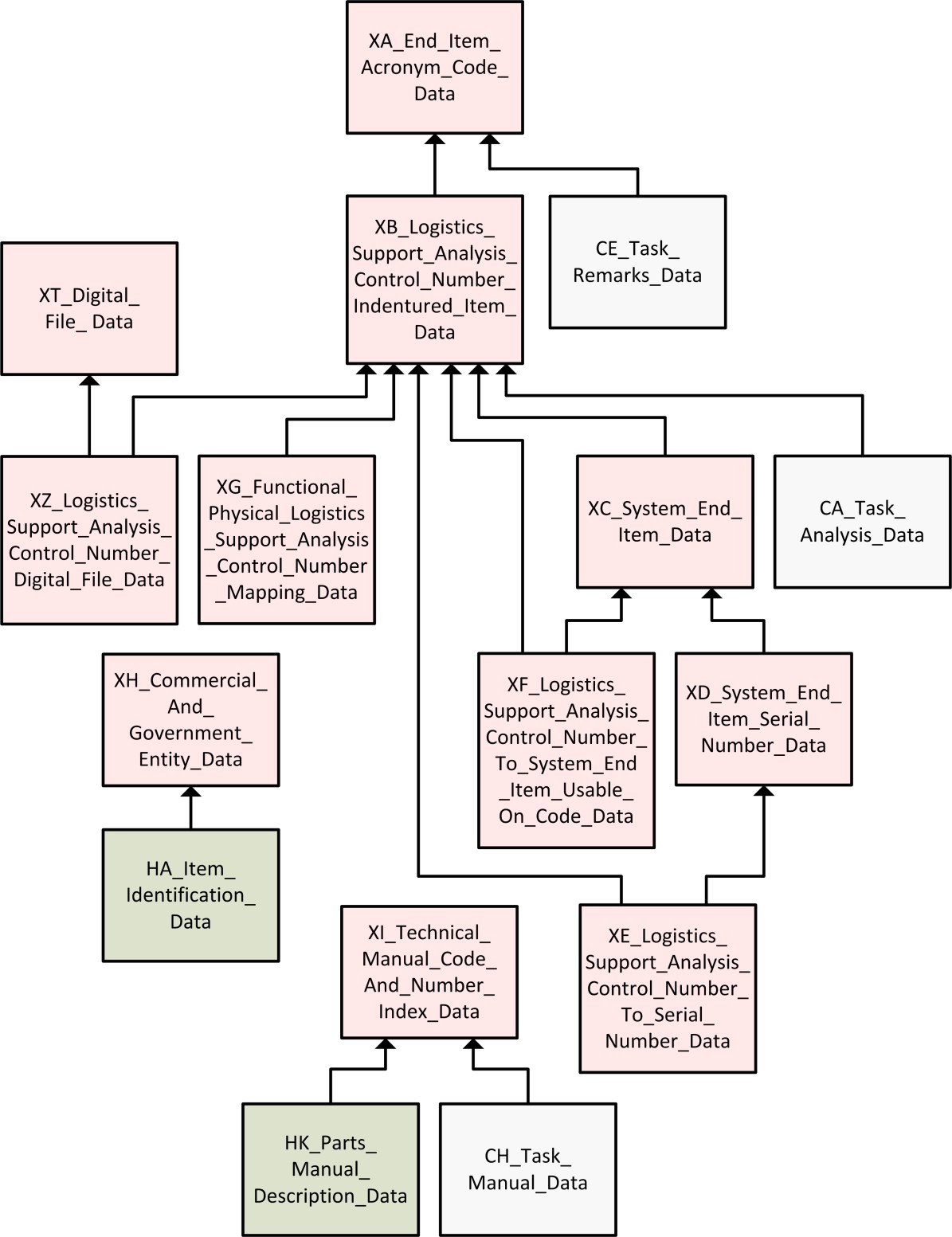
XB_Logistics_Support_Analysis_Control_Number_Indentured_Item_data
Class Relationship Diagram
X
XB Logistics Support Analysis Control Number Indentured Item
Description
This entity contains all LCNs and information about the indentured location of the LCN in the hardware/functional configuration of the system/equipment.
a) If LCN Structure from entity XA is blank, LCN Indenture Code is mandatory.
b) If LCN Structure is not blank, the LCN must match an indenture level length specified by the LCN Structure, or be a greater length than the total of all LCN Structure indenture levels, e.g., if the LCN Structure is "1223323", an LCN must have a length of 1, 3, 5, 8, 11, 13, 16 or greater than 16 positions (up to 18). If the LCN structure will exceed the 18 character limit of the LCN field then the rule in paragraph a, above, will apply.
Child of Class
XA_End_Item_Acronym_Code_data
Key Properties
Additional Properties
logistics_support_analysis_control_number_indenture_code
logistics_support_analysis_control_number_nomenclature
reliability_availability_and_maintainability_indicator
sectionalized_item_transportation_indicator
system_end_item_identifier
technical_manual_functional_group_code
document_code
work_area_code_zone
Class
XC_System_End_Item_data
Class Relationship Diagram
X
XC System End Item
Description
This entity contains only those LCNs representing a system/End Item (EI) or an "A" indenture-coded item. A system/EI is an item capable of independent operation for its intended use, e.g., rifle, radio receiver, or is a class or group of equipment that is managed and provisioned under a separate Provisioning Contract Control Number (PCCN).
a) The system/EI Identifier of "S" or "E" identifies LCNs representing system/EIs from entity XB for entry into this entity.
b) For identical Provisioning Contract Control Numbers the UOCs must be different.
c) All alternate assemblies of the same LCN must have the same PCCN.
d) No two items under the same Provisioning Contract Control Numbers can have the same Provisioning List Item Sequence Number (PLISN).
e) Usable on code and PCCN are mandatory for each LCN identified as a system/EI.
Child of Class
XB_Logistics_Support_Analysis_Control_Number_Indentured_Item_data
Key Properties
Additional Properties
system_end_item_provisioning_contract_control_number
usable_on_code
quantity_per_end_item_calculation_option_code
system_end_item_item_designator_code
system_end_item_provisioning_list_item_sequence_number
system_end_item_quantity_per_assembly
system_end_item_quantity_per_end_item
system_end_item_type_of_change_code
transportation_end_item_indicator
Class
XD_System_End_Item_Serial_Number_data
Class Relationship Diagram
X
XD System End Item Serial Number
Description
This entity is only used when parts configuration control is managed by serial numbers (S/N) of a system/EI. It contains Serial Numbers applicable to a System/End Item, and if required, Serial Number UOC assignments, e.g., for model V10, identified in entity XC, applicable serial numbers may be 110 through 118, 121 and 125-130, while for model V10A, also identified in entity XC, the applicable serial numbers may be 119, 122-124, and 131-150.
Example
Child of Class
XC_System_End_Item_data
Key Properties
Additional Properties
Class
XE_Logistics_Support_Analysis_Control_Number_to_Serial_Number_Usable_On_Code_data
Class Relationship Diagram
X
XE Logistics Support Analysis Control Number to Serial Number Usable On Code
Description
This entity contains LCN and system/EI S/N LCNs in order to determine the associated S/N and S/N UOCs for the LCN. Entity keys include all attributes.
Child of Class
XB_Logistics_Support_Analysis_Control_Number_Indentured_Item_data
XD_System_End_Item_Serial_Number_data
Key Properties
end_item_acronym_code
serial_number_item_logistics_support_analysis_control_number
serial_number_item_alternate_logistics_support_analysis_control_number_code
serial_number_item_logistics_support_analysis_control_number_type
serial_number_system_logistics_support_analysis_control_number
serial_number_system_alternate_logistics_support_analysis_control_number_code
serial_number_system_logistics_support_analysis_control_number_type
serial_number_from
serial_number_to
Class
XF_Logistics_Support_Analysis_Control_Number_to_System_End_Item_Usable_On_Code_data
Class Relationship Diagram
X
XF Logistics Support Analysis Control Number to System End Item Usable On Code
Description
This entity contains LCNs and system/EI LCNs in order to determine the associated UOC for the LCN. This entity and entity HO (for provisioning) are critical to qualify an LCN for data exchange set requests when a specific UOC is required for the data exchange set. Keys include all attributes.
Child of Class
XB_Logistics_Support_Analysis_Control_Number_Indentured_Item_data
XC_System_End_Item_data
Key Properties
end_item_acronym_code
usable_on_code_item_logistics_support_analysis_control_number
usable_on_code_item_alternate_logistics_support_analysis_control_number_code
usable_on_code_item_logistics_support_analysis_control_number_type
usable_on_code_system_logistics_support_analysis_control_number
usable_on_code_system_alternate_logistics_support_analysis_control_number_code
usable_on_code_system_logistics_support_analysis_control_number_type
Class
XG_Functional_Physical_Logistics_Support_Analysis_Control_Number_Mapping_data
Class Relationship Diagram
X
XG Functional Physical Logistics Support Analysis Control Number Mapping
Description
This entity contains a cross-listing of functional/physical LCNs. Physical LCN Type must always be coded "P"; Functional LCN Type must always be coded "F". When a functional and physical LCN are mapped through this entity, all data contained against the functional LCN shall migrate to the physical LCN (physical LCN data shall take precedence if data duplication has occurred). After the data is migrated, data additions and updates for this item shall only occur against the physical LCN.
Child of Class
XB_Logistics_Support_Analysis_Control_Number_Indentured_Item_data
Key Properties
Class
XH_Commercial_and_Government_Entity_data
Class Relationship Diagram
X
XH Commercial and Government Entity
Description
This entity contains all Commercial and Government Entity (CAGE) codes and the CAGE addresses. A CAGE street, city, state, nation, or postal zone cannot be included without a CAGE name.
Example
Key Properties
Class
XI_Technical_Manual_Code_and_Number_Index_data
Class Relationship Diagram
X
XI Technical Manual Code and Number Index
Description
This entity contains a crossreference of Technical Manual (TM) code to TM number(s).
Key Properties
Additional Properties
Class
XT_Digital_File_data
Class Relationship Diagram
X
XT Digital File
Description
This entity contains elements to describe a file,document, image, or other electronic medium. The document_id can contain an Information Control Number or digital file identifier. In the latter case the originator_code must be the associated commercial_and_government_entity_code. Drawing and Document File Extension must either both be blank, or both have entries.
Key Properties
Additional Properties
Class
XZ_Logistics_Support_Analysis_Control_Number_Digital_File_data
Class Relationship Diagram
X
XZ Logistics Support Analysis Control Number Digital File
Description
This entity contains elements to associate or map a document, image, or other electronic medium to a particular logistics_support_analysis_control_number.
Child of Class
XB_Logistics_Support_Analysis_Control_Number_Indentured_Item_data
XT_Digital_File_data
Class
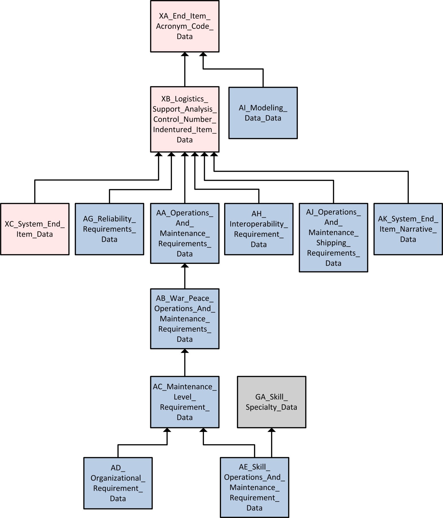
AA_Operations_and_Maintenance_Requirements_data
Class Relationship Diagram
X
AA Operations and Maintenance Requirements
Description
This entity identifies operations, maintenance, and reliability requirements for the new system/equipment by the service designator code. For a given entity instance of information, Required Percentile is not allowed without a Maximum Time to Repair.
Child of Class
XB_Logistics_Support_Analysis_Control_Number_Indentured_Item_data
Key Properties
Additional Properties
crew_size
number_operation_locations
operational_mean_active_maintenance_downtime
reliability_centered_maintenance_logic_utilized
required_achieved_availiability
required_inherent_availiability
required_maximum_time_to_repair
required_operational_mean_time_to_repair
required_percentile
required_technical_mean_time_to_repair
technical_mean_active_maintenance_downtime
total_systems_supported
Class
AB_War_Peace_Operations_and_Maintenance_Requirement_data
Class Relationship Diagram
X
AB War Peace Operations and Maintenance Requirement
Description
This entity identifies O/M requirements for the new system/equipment based on its projected wartime and peacetime missions for a given service designator code. For a given entity instance, Mean Mission Duration and Mean Mission Duration Measurement Base must either both be blank, or both have entries.
Child of Class
AA_Operations_and_Maintenance_Requirements_data
Key Properties
Class
AC_Maintenance_Level_Requirement_data
Class Relationship Diagram
X
AC Maintenance Level Requirement
Description
This entity identifies O/M requirements for the new system/equipment by O/M level, wartime/peacetime scenario, and service designator code. For a given entity instance, Maintenance Level Percentile is not allowed without a Maintenance Level Maximum Time to Repair.
Example
Child of Class
AB_War_Peace_Operations_and_Maintenance_Requirement_data
Key Properties
Additional Properties
maintenance_level_maximum_time_to_repair
maintenance_level_percentile
maintenance_level_scheduled_annual_man_hours
maintenance_level_unscheduled_annual_man_hours
number_of_systems_supported
scheduled_man_hour_per_operating_hour
unscheduled_maintenance_mean_elapsed_time
unscheduled_maintenance_mean_man_hours
unscheduled_man_hour_per_operating_hour
Class
AD_Organizational_Level_Requirement_data
Class Relationship Diagram
X
AD Organizational Level Requirement
Description
This entity identifies organizational level O/M requirements for the new system/equipment by wartime/peacetime scenario, O/M level, and service designator code. For a given entity instance, only "C" and "O" for the O/M Level Code are allowed for this entity.
Example
Child of Class
AC_Maintenance_Level_Requirement_data
Key Properties
Additional Properties
daily_inspection_mean_elapsed_time
daily_inspection_mean_man_hours
mission_profile_change_mean_elapsed_time
mission_profile_change_mean_man_hours
periodic_inspection_mean_elapsed_time
periodic_inspection_mean_man_hours
postoperative_inspection_mean_elapsed_time
postoperative_inspection_mean_man_hours
preoperative_inspection_mean_elapsed_time
preoperative_inspection_mean_man_hours
turnaround_inspection_mean_elapsed_time
turnaround_inspection_mean_man_hours
Class
AE_Skill_Operations_and_Maintenance_Requirement_data
Class Relationship Diagram
X
AE Skill Operations and Maintenance Requirement
Description
This entity identifies operational maintenance manpower constraints by Skill Specialty Code (SSC) at specific O/M levels given a wartime/peacetime scenario and service designator code.
Child of Class
AC_Maintenance_Level_Requirement_data
GA_Skill_Specialty_data
Key Properties
Additional Properties
Class
AG_Reliability_Requirement_data
Class Relationship Diagram
X
AG Reliability Requirement
Description
This entity identifies reliability requirement parameters for the new system/equipment that are dependent on measurement base (MB). There can be multiple entities depending upon the annual operating requirements MB. For a given entity instance of information, the following cross-element edits apply to entity AG:
a) AOR and AOR MB must either both be blank, or both have entries.
b) Reliability Operational Requirements Indicator must match Operational Requirements Indicator in Entity AB for the given keys. The keys consist of EIAC, LCN, ALC, and LCN Type.
Child of Class
XB_Logistics_Support_Analysis_Control_Number_Indentured_Item_data
Key Properties
Additional Properties
annual_operating_requirement
reliability_operational_requirements_indicator
required_mean_time_between_removals
required_mean_time_between_effective_function_failures
required_mean_time_between_noneffective_function_failures
required_mean_time_between_system_aborts
required_operational_mean_time_between_failures
required_operational_mean_time_between_maintenance_actions
required_technical_mean_time_between_failures
required_technical_mean_time_between_maintenance_actions
Class
AH_Interoperability_Requirement_data
Class Relationship Diagram
X
AH Interoperability Requirement
Description
This entity identifies item name, National Stock Number (NSN), and the TM of the system/equipment with which the new system/equipment must be able to be transported by/interoperate with. For a given entity instance of information, the following cross-element edits apply to entity AH:
a) Interoperable CAGE Number and Interoperable Reference Number must either both be blank, or both have entries.
b) Interoperable Item National Item Identification Number (NIIN) and Interoperable Item Federal Supply Classification (FSC) must either both be blank, or both have entries.
Example
Child of Class
XB_Logistics_Support_Analysis_Control_Number_Indentured_Item_data
Key Properties
Class
AI_Modeling_Data_data
Class Relationship Diagram
X
AI Modeling Data
Description
This entity documents maintenance level specific information, for a given service designator code, to be used for logistics modeling. For a given set of modeling data, the following rules apply:
a) labor rate and currency_code must either both be blank, or both have entries.
b) repair work space cost and currency code must either both be blank, or both have entries.
Child of Class
XA_End_Item_Acronym_Code_data
Key Properties
Class
AJ_Operations_and_Maintenance_Shipping_Requirements_data
Class Relationship Diagram
X
AJ Operations and Maintenance Shipping Requirements
Description
This entity identifies the O/M level from which a spare/repair part is shipped and the O/M level that receives the part.
Child of Class
XB_Logistics_Support_Analysis_Control_Number_Indentured_Item_data
Key Properties
Additional Properties
Class
AK_System_End_Item_Narrative_data
Class Relationship Diagram
X
AK System End Item Narrative
Description
This entity identifies Additional Supportability Considerations, Additional Supportability Parameters, and Operational Mission Failure Definition.
Child of Class
XB_Logistics_Support_Analysis_Control_Number_Indentured_Item_data
Key Properties
Class
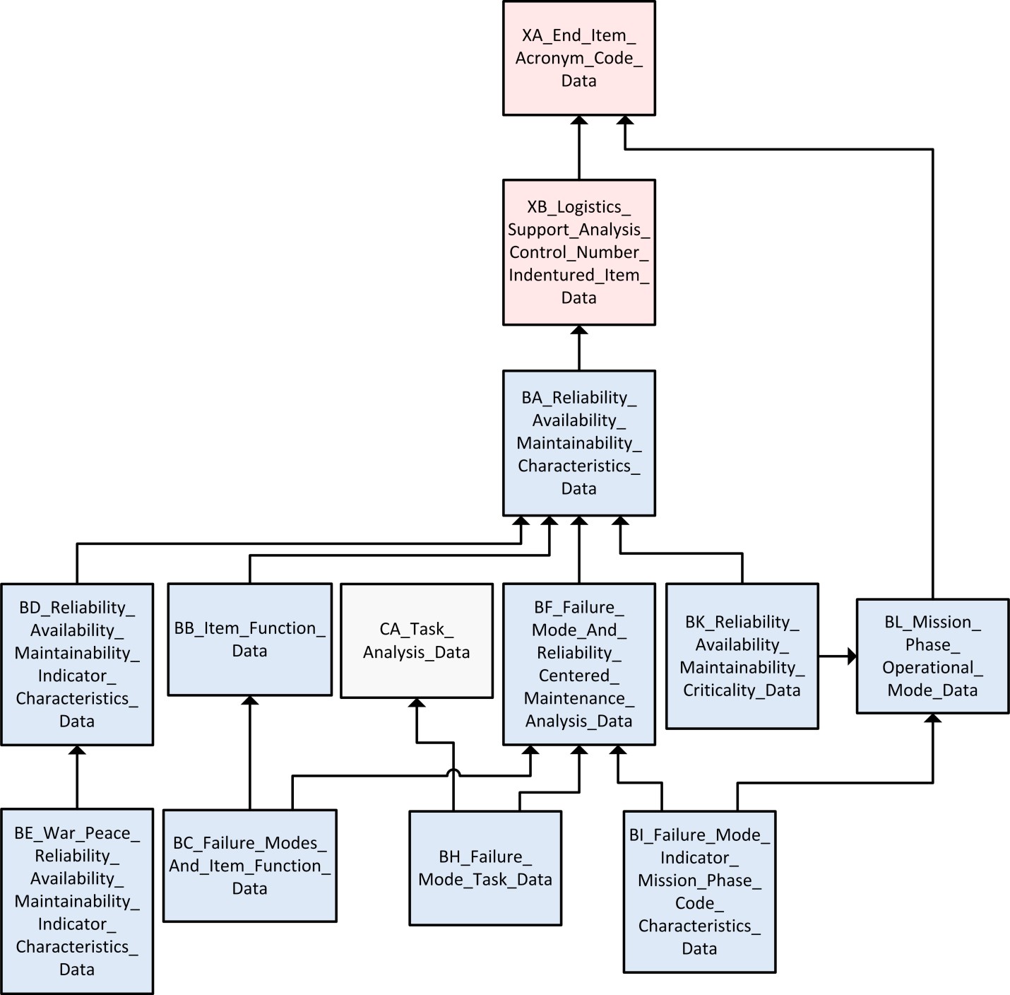
BA_Reliability_Availability_and_Maintainability_Characteristics_data
Class Relationship Diagram
X
BA Reliability Availability and Maintainability Characteristics
Description
This entity contains logistics considerations, maintenance, and reliability characteristics of the item under analysis. This entity contains narrative information associated with logistics considerations. For a given entity instance of information, the following cross-element edits apply to entity BA:
a) The Reliability, Availability and Maintainability (RAM) area can only be used if a (Y) is entered in the RAM Indicator attribute of Entity XB.
b) Fault Isolation Percent Failure Group 1 is not allowed without Fault Isolation Ambiguity Group 1.
c) The combination in (b) is not allowed without Built in Test Detection Level Percent Group 1.
d) That which applies for the combinations in Group 1 (b,
c) also applies to the combination in group 2.
e) Wearout Life and Wearout Life MB, both must be blank, or both must have entries.
Child of Class
XB_Logistics_Support_Analysis_Control_Number_Indentured_Item_data
Key Properties
Additional Properties
built_in_test_cannot_duplicate_percentage
built_in_test_detectability_level_percentage_group_1
built_in_test_detectability_level_percentage_group_2
built_in_test_retest_ok_percent
conversion_factor
failure_rate_data_source
fault_isolation_ambiguity_group_1
fault_isolation_ambiguity_group_2
fault_isolation_percent_failure_group_1
fault_isolation_percent_failure_group_2
logistics_considerations_accessibility
logistics_considerations_connectors
logistics_considerations_corrosion_rust_control
logistics_considerations_design_for_self_protection
logistics_considerations_fault_location
logistics_considerations_labeling
logistics_considerations_maintenance_ease
logistics_considerations_packaging_and_transportation
logistics_considerations_safety
logistics_considerations_skills
logistics_considerations_standardization
logistics_considerations_test_points
logistics_considerations_training
minimum_equipment_list_indicator
pilot_rework_overhaul_candidate
security_clearance
support_concept
wearout_life
wearout_life_measurement_base
reliability_availability_and_maintainability_maintenance_concept_narrative
reliability_availability_and_maintainability_minimum_equipment_list_narrative
reliability_availability_and_maintainability_qualitative_and_quantitative_maintainability_requirements_narrative
reliability_availability_and_maintainability_maintenance_plan_rationale_narrative
logistics_considerations_for_standardization_narrative
logistics_considerations_for_accessibility_narrative
logistics_considerations_for_maintenance_ease_narrative
logistics_considerations_for_safety_narrative
logistics_considerations_for_test_points_narrative
logistics_considerations_for_skills_narrative
logistics_considerations_for_training_narrative
logistics_considerations_for_connectors_for_ease_of_removal_narrative
logistics_considerations_for_packaging_and_transportation_narrative
logistics_considerations_for_fault_location_narrative
logistics_considerations_for_labeling_narrative
logistics_considerations_for_design_for_self_protection_narrative
logistics_considerations_for_corrosion_and_rust_control_narrative
system_redesign_standardization_narrative
system_redesign_accessibility_narrative
system_redesign_maintenance_ease_narrative
system_redesign_safety_narrative
system_redesign_test_points_narrative
system_redesign_skills_narrative
system_redesign_training_narrative
system_redesign_connectors_for_ease_of_removal_narrative
system_redesign_packaging_and_transportation_narrative
system_redesign_fault_location_narrative
system_redesign_labeling_narrative
system_redesign_for_self_protection_narrative
system_redesign_corrosion_and_rust_control_narrative
Class
BB_Item_Function_data
Class Relationship Diagram
X
BB Item Function
Description
This entity contains the individual item functions for the item under analysis.
Child of Class
BA_Reliability_Availability_and_Maintainability_Characteristics_data
Key Properties
Additional Properties
Class
BC_Failure_Modes_and_Item_Function_data
Class Relationship Diagram
X
BC Failure Modes and Item Function
Description
This entity associates each failure with one or more item functions for the item under analysis.
Child of Class
BB_Item_Function_data
Class
BD_Reliability_Availability_and_Maintainability_Indicator_Characteristics_data
Class Relationship Diagram
X
BD Reliability Availability and Maintainability Indicator Characteristics
Description
This entity contains reliability and maintainability characteristics of the item under analysis categorized by comparative analysis, allocated, predicted, or measured values. For a given LCN, ALC, and LCN Type combination, each different measurement base must remain constant for all RAM Indicator Codes. For a given entity instance of information, the following cross-element edits apply to entity BD:
a) Failure Rate and Failure Rate MB must either both be blank, or both have entries.
b) Percentile is not allowed without a Maximum Time to Repair.
c) Mean Time Between Failures Operational and Mean Time Between Failures Operational MB must either both be blank, or both have entries.
d) Mean Time Between Failures Technical and Mean Time Between Failures Technical MB must either both be blank, or both have entries.
e) Mean Time Between Maintenance Actions Operational and Mean Time Between Maintenance Actions Operational MB must either both be blank, or both have entries.
f) Mean Time Between Maintenance Actions Technical and Mean Time Between Maintenance Actions Technical MB must either both be blank, or both have entries.
g) Mean Time Between Maintenance Induced and Mean Time Between Maintenance Induced MB must either both be blank, or both have entries.
h) Mean Time Between Maintenance Inherent and Mean Time Between Maintenance Inherent MB must either both be blank, or both have entries.
i) Mean Time Between Maintenance No Defect and Mean Time Between Maintenance No Defect MB must either both be blank, or both have entries.
j) Mean Time Between Preventive Maintenance and Mean Time Between Preventive Maintenance MB must either both be blank, or both have entries.
k) Mean Time Between Removals and Mean Time Between Removals MB must either both be blank, or both have entries.
l) Mean Time Between System Aborts and Mean Time Between System Aborts MB must either both be blank, or both have entries.
m) Mean Time Between Effective Function Failures and Mean Time Between Effective Function Failures MB must either both be blank, or both have entries.
n) Mean Time Between Noneffective Function Failures and Mean Time Between Nonffective Function Failures MB must either both be blank, or both have entries.
o) Achieved Availability shall be calculated based on Mean Time Between Failure Technical (Entity BD), Mean Time Between Maintenance - No Defect (Entity BD), Mean Time Between Preventive Maintenance (Entity BD), Elapsed Time (Entity CA), and Task Frequency (CA). A change in any of these variables shall result in an update of the Achieved Availability (Entity BD).
p) Inherent Availability shall be calculated based on Mean Time Between Failures Technical (Entity BD) and Mean Time To Repair Technical (Entity BD). A change in any of these variables shall result in an update of the Inherent Availability (Entity BD).
Child of Class
BA_Reliability_Availability_and_Maintainability_Characteristics_data
Key Properties
Additional Properties
achieved_availability
failure_rate
failure_rate_measurement_base
inherent_availability
inherent_maintenance_factor
maximum_time_to_repair
mean_time_between_failure_operational_measurement_base
mean_time_between_failure_technical_measurement_base
mean_time_between_failures_operational
mean_time_between_failures_technical
mean_time_between_maintenance_actions_operational
mean_time_between_maintenance_actions_operational_measurement_base
mean_time_between_maintenance_actions_technical
mean_time_between_maintenance_actions_technical_measurement_base
mean_time_between_maintenance_induced
mean_time_between_maintenance_induced_measurement_base
mean_time_between_maintenance_inherent
mean_time_between_maintenance_inherent_measurement_base
mean_time_between_maintenance_no_defect
mean_time_between_maintenance_no_defect_measurement_base
mean_time_between_preventive_maintenance
mean_time_between_preventive_maintenance_measurement_base
mean_time_between_removals
mean_time_between_removals_measurement_base
mean_time_to_repair_operational
mean_time_to_repair_technical
mean_time_between_system_aborts
mean_time_between_system_aborts_measurement_base
mean_time_between_effective_function_failures
mean_time_between_effective_function_failures_measurement_base
mean_time_between_noneffective_function_failures
mean_time_between_noneffective_function_failures_measurement_base
percentile
Class
BE_War_Peace_Reliability_Availability_and_Maintainability_Indicator_Characteristics_data
Class Relationship Diagram
X
BE War Peace Reliability Availability and Maintainability Indicator Characteristics
Description
This entity contains reliability and maintainability characteristics of the item under analysis categorized by wartime/peacetime scenarios and comparative, allocated, predicted, or measured values.
Child of Class
BD_Reliability_Availability_and_Maintainability_Indicator_Characteristics_data
Key Properties
end_item_acronym_code
logistics_support_analysis_control_number
alternate_logistics_support_analysis_control_number_code
logistics_support_analysis_control_number_type
reliability_availability_and_maintainability_operational_requirement_indicator
reliability_availability_and_maintainability_indicator_code
Additional Properties
Class
BF_Failure_Mode_and_Reliability_Centered_Maintenance_Analysis_data
Class Relationship Diagram
X
BF Failure Mode and Reliability Centered Maintenance Analysis
Description
This entity contains failure mode information and reliability centered maintenance analysis results associated with the item under analysis failure modes. This entity may be used to identify Failure/Damage Mode Effect End Effect, Failure/Damage Mode Effect Local, Failure/Damage Mode Effect Next Higher, Failure Cause, Failure/Damage Mode, Failure Mode Detection Method, Failure Mode Predictability, Failure Mode Remarks, Reliability Centered Maintenance (RCM) Redesign Recommendations, and RCM Reasoning. For a given entity instance of information, the following cross-element edits apply to entity BF:
a) Engineering Failure Mode Mean Time Between Failure and Engineering Failure Mode Mean Time Between Failure MB must either both be blank, or both have entries.
b) Engineering Failure Mode Mean Time Between Failure shall be calculated based on Failure Mode Ratio (Entity BF) and Part Failure Rate (Entity BD). A change in any of these variables shall result in an update of the Engineering Failure Mode Mean Time Between Failure (Entity BF).
Child of Class
BA_Reliability_Availability_and_Maintainability_Characteristics_data
Key Properties
Additional Properties
engineering_failure_mode_mean_time_between_failure
engineering_failure_mode_mean_time_between_failure_measurement_base
failure_mode_classification
failure_mode_ratio
reliability_centered_maintenance_disposition_a
reliability_centered_maintenance_disposition_b
reliability_centered_maintenance_disposition_c
reliability_centered_maintenance_disposition_d
reliability_centered_maintenance_disposition_e
reliability_centered_maintenance_disposition_f
reliability_centered_maintenance_disposition_g
reliability_centered_maintenance_disposition_h
reliability_centered_maintenance_disposition_i
reliability_centered_maintenance_disposition_j
reliability_centered_maintenance_logic_results_01
reliability_centered_maintenance_logic_results_02
reliability_centered_maintenance_logic_results_03
reliability_centered_maintenance_logic_results_04
reliability_centered_maintenance_logic_results_05
reliability_centered_maintenance_logic_results_06
reliability_centered_maintenance_logic_results_07
reliability_centered_maintenance_logic_results_08
reliability_centered_maintenance_logic_results_09
reliability_centered_maintenance_logic_results_10
reliability_centered_maintenance_logic_results_11
reliability_centered_maintenance_logic_results_12
reliability_centered_maintenance_logic_results_13
reliability_centered_maintenance_logic_results_14
reliability_centered_maintenance_logic_results_15
reliability_centered_maintenance_logic_results_16
reliability_centered_maintenance_logic_results_17
reliability_centered_maintenance_logic_results_18
reliability_centered_maintenance_logic_results_19
reliability_centered_maintenance_logic_results_20
reliability_centered_maintenance_logic_results_21
reliability_centered_maintenance_logic_results_22
reliability_centered_maintenance_logic_results_23
reliability_centered_maintenance_logic_results_24
reliability_centered_maintenance_logic_results_25
failure_damage_mode_effect_end_effect_narrative
failure_damage_mode_effect_local_narrative
failure_damage_mode_effect_next_higher_narrative
failure_cause_narrative
failure_damage_mode_narrative
failure_mode_detection_method_narrative
failure_mode_predictability_narrative
failure_mode_remarks_narrative
failure_mode_redesign_recommendations_narrative
reliability_centered_maintenance_age_exploration_narrative
reliability_centered_maintenance_reasoning_narrative
reliability_centered_maintenance_redesign_recommendation_narrative
Class
BH_Failure_Mode_Task_data
Class Relationship Diagram
X
BH Failure Mode Task
Description
This entity identifies the maintenance task(s) that are required to correct the identified failure mode of the item under analysis and preventative maintenance tasks that are deemed applicable and effective through an RCM analysis. For a given entity instance of information, the following cross-element edits apply to entity BH:
a) The EIAC from Task Requirement Entity CA and Failure Mode and RCM Analysis Entity BF are the same; therefore, they are not duplicated.
b) Entity keys are migrated from entity BF, but are given the role name "FMT" to distinguish them. Entity keys are migrated from entity CA, but are given the role name "Task Requirement" to distinguish them.
c) Maintenance Interval and Maintenance Interval MB must either both be blank, or both have entries.
d) Edit c is not allowed unless a preventive Task Type is selected.
e) Task Type must be "P" or "U", if Preventive Maintenance Checks and Services (PMCS) from the CA entity is "Y".
Child of Class
BF_Failure_Mode_and_Reliability_Centered_Maintenance_Analysis_data
CA_Task_Requirement_data
Key Properties
end_item_acronym_code
failure_mode_task_logistics_support_analysis_control_number
failure_mode_task_alternate_logistics_support_analysis_control_number_code
failure_mode_task_logistics_support_analysis_control_number_type
failure_mode_task_failure_mode_indicator
task_requirement_logistics_support_analysis_control_number
task_requirement_alternate_logistics_support_analysis_control_number_code
task_requirement_logistics_support_analysis_control_number_type
task_code
Additional Properties
Class
BI_Failure_Mode_Indicator_Mission_Phase_Code_Characteristics_data
Class Relationship Diagram
X
BI Failure Mode Indicator Mission Phase Code Characteristics
Description
This entity contains FMECA results associated with the item under analysis categorized by failure mode and mission phase/operational mode. This entity may be used to identify Compensating Design Provisions and Compensating Operator Actions. For a given entity instance of information, the following cross-element edits apply to entity BI:
a) The EIAC from Mission Phase Operational Mode Entity BL and Failure Mode Entity BF are the same; therefore, they are not duplicated.
b) Operating Time and Operating Time MB must either both be blank, or both have entries.
c) The Operating Time MB should be the same as the Failure Rate MB from entity BD for the calculations to be correct.
d) Failure Mode Criticality Number shall be calculated based on Failure Effect Probability (Entity BI), Failure Mode Ratio (Entity BI), Part Failure Rate (Entity BD), and Operating Time (Entity BI). A change in any of these variables shall result in an update of the Failure Mode Criticality Number (Entity BI).
e) The element Failure Mode Indicator Mission CharacteristicsCompensating Design Provisions describes compensating design provisions that circumvent or mitigate the effect of the failure (Compensating Design Provisions). It is a record of the true behavior of the item in the presence of an internal malfunction or failure. It describes features of the design at any indenture level that will nullify the effects of a malfunction or failure, control or deactivate system items to halt generation or propagation of failure effects, or activate backup or standby items or systems. Redesign compensating provisions include:
1) Redundant items that allow continued and safe operation.
2) Safety or relief devices such as monitoring or alarm provisions that permit effective operation or limit damage.
3) Alternate models of operation such as backup or standby items or systems.
f) The element Failure Mode Indicator Mission Characteristics Compensating Operator Action Provisions Narrative describes compensating operator action provisions that circumvent or mitigate the effect of the postulated failure (Compensating Operator Action Provisions). It describes the compensating provision that best satisfies the indication(s) observed by an operator when the failure occurs, and the consequences of any probable incorrect action(s) by the operator in response to an abnormal indication.
Child of Class
BF_Failure_Mode_and_Reliability_Centered_Maintenance_Analysis_data
BL_Mission_Phase_Operational_Mode_data
Key Properties
Additional Properties
failure_effect_probability
failure_mode_criticality_number
failure_probability_level
operating_time
operating_time_measurement_base
safety_hazard_severity_code
failure_mode_indicator_mission_characteristics_compensating_design_provisions_narrative
failure_mode_indicator_mission_characteristics_compensating_operator_action_provisions_narrative
Class
BK_Reliability_Availability_and_Maintainability_Criticality_data
Class Relationship Diagram
X
BK Reliability Availability and Maintainability Criticality
Description
This entity sums up the failure mode criticality numbers related to the failure modes of an item within specific safety hazard severity classification (SHSC) and mission phases. The Item Criticality Number shall be calculated based on the summation of the Failure Mode Criticality Numbers (Entity BI).
a) A change in any of the Failure Mode Criticality Numbers (Entity BI) shall result in an update of the Item Criticality Number (Entity BK).
b) Safety Hazard Severity Code must be established in entity BI prior to establishing a RAM Safety Hazard Severity Code in this entity.
Child of Class
BA_Reliability_Availability_and_Maintainability_Characteristics_data
Key Properties
Additional Properties
Class
BL_Mission_Phase_Operational_Mode_data
Class Relationship Diagram
X
BL Mission Phase Operational Mode
Description
This entity identifies the mission phase/operational modes that the new system/equipment is expected to experience during normal operation.
Example
Child of Class
XA_End_Item_Acronym_Code_data
Key Properties
Additional Properties
Class
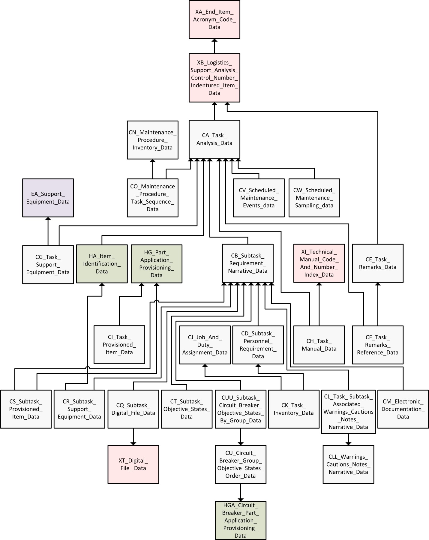
CA_Task_Requirement_data
Class Relationship Diagram
X
CA Task Requirement
Description
This entity contains task level information such as Mean Elapsed Time, Task Frequency, Task Criticality, Task Identification (ID) and Task Code. It also contains information about personnel and training aspects of the task. In addition, this entity provides the capability to reference an entire task.
a) For referencing purposes only, Referenced LCN, Referenced LCN Type, Referenced ALC, Referenced EIAC, and Referenced Task Code are mandatory keys. This referencing capability should only be used when the data of this entity and the subordinate Entities (Entities CB through CI, CR and CS) are the same for referenced and referencing tasks. All non-mandatory attributes in Entity CA and all subordinate Entities (Entities CB, CI, CR, and CS) are pulled from the Referenced Task and its subordinate Entities. Key attributes entered in Entity CA will migrate to all subordinate Entities; but, additional keys that are needed in subordinate Entities will be pulled from the Referenced Task and its subordinate Entities. In other words, only key entries and referenced entries are required in this entity and no further entries are required in subordinate Entities.
b) Unscheduled task codes, task interval codes of "F", "G", or "J" (2nd position of the task code), must have an MB entered that corresponds to the MB for the AOR. For this reason, the AOR LCN, AOR ALC, AOR LCN Type, and the AOR MB must match with a set of key values already established in Entity AG.
c) Every Task Code must have a Task ID.
d) Secondary Means of Detection is not allowed without Primary Means of Detection.
e) Up to three Performance Standards and Task Conditions can be entered for a given entity instance.
f) Every Task Code requires a corresponding task frequency.
g) If the Facility Requirement Code is "Y", the Facility Entities (F Entities) should be addressed.
h) Up to four Training Location Rationale codes may be entered for each unique combination of LCN, EIAC, ALC, LCN Type, and Task Code (codes must be entered in a continuous string).
i) Up to four Training Rationale codes may be entered for each unique combination of LCN, EIAC, ALC, LCN Type and Task Code (codes must be entered in a continuous string).
j) Measured/Predicted Mean Man-Hours are calculated by summing the Measured/Predicted Mean Man-Minutes per Person ID for the given task and dividing by 60.
k) Measured Mean Elapsed Time is calculated by summing the Mean Minute Elapsed Times for all subtasks of a task and dividing by 60.
l) Task Frequency (corrective) shall be calculated based on Failure Mode Ratio (Entity BF), Failure Rate (Entity BD), Mean Time Between Maintenance Induced (Entity BD), Mean Time Between Maintenance No Defect (Entity BD), Conversion Factor (Entity BA), and Annual Operating Requirements (Entity AG). Task Frequency (preventive) shall be calculated based on Annual Operating Requirements (Entity AG), Conversion Factor (Entity BA), Maintenance Interval (Entity BH), Task Interval Code (Entity CA) or scheduled events (Entities CV and CW). A change in any of these variables shall result in an update of Task Frequency (Entity CA).
Child of Class
XB_Logistics_Support_Analysis_Control_Number_Indentured_Item_data
Key Properties
Additional Properties
annual_operating_requirement_alternate_logistics_support_analysis_control_number_code
annual_operating_requirement_logistics_support_analysis_control_number
annual_operating_requirement_logistics_support_analysis_control_number_type
facility_requirement_code
hardness_critical_procedure_code
hazardous_maintenance_procedure_code
measured_mean_elapsed_time
measured_mean_man_hours
predicted_mean_elapsed_time
predicted_mean_man_hours
preventive_maintenance_checks_and_services_indicator_code
primary_means_of_detection
referenced_alternate_logistics_support_analysis_control_number_code
referenced_end_item_acronym_code
referenced_logistics_support_analysis_control_number
referenced_logistics_support_analysis_control_number_type
referenced_task_code
secondary_means_of_detection
task_annual_operating_requirements_measurement_base
task_condition_a
task_condition_b
task_condition_c
task_criticality_code
task_frequency
task_performance_standard_a
task_performance_standard_b
task_performance_standard_c
task_identification
tool_support_equipment_requirement_code
training_equipment_requirement_code
training_location_rationale
training_rationale
training_recommendation_type
Class
CB_Subtask_Requirement_Narrative_data
Class Relationship Diagram
X
CB Subtask Requirement Narrative
Description
This entity contains data related to the subtask level such as Work Area Code and Mean Minute Elapsed Time. All task narrative will be written at the subtask level, and then rolled into the task level. It is possible to reference subtask descriptions within this entity. This entity contains the sequential task narrative entered at the subtask level. The narrative will be entered in a step-by-step basis in order to document all subtasks required to perform the task under analysis. Subtasks should be detailed and sequenced to eliminate possibilities of technically incorrect procedures. Elements are subordinate to subtasks. All requirements for power, compressed air, and environmental considerations will be specified. Qualifying notes must be included when performance to particular standards, survivability requirements, inspection criteria, special procedures, tolerances, measurement ranges, cautions and safety precautions are required. Notes and warnings for set up of tasks (e.g., identifying support items that need to be on hand and ready, but are not needed until later in the task) should be documented in the first subtask. Similarly, notes and warnings for close- down of a task should be documented in the last subtask. In cases of multi-personnel tasks, the communication and coordination requirements between personnel must be documented (i.e., communication and coordination between individuals in one crew area with individuals in another area).
a) For referencing purposes, Referenced Subtask Number, Referenced Subtask Task Code, Referenced Subtask LCN, Referenced Subtask ALC, Referenced Subtask LCN Type, and Referenced Subtask EIAC must be included as non-identifying keys. This referencing capability should only be used when the data of this entity and the referenced sequential task description, subtask personnel requirements (Entity CD), subtask support equipment data (Entity CR), and subtask provisioned item data (Entity CS) are the same for referenced and referencing subtasks. All non-key attributes in entity CB and its subordinate entities CD, CR, and CS are pulled from the referenced subtask and its subordinate entities. Keys from entity CB migrate down to Entities CD, CR and CS. Additional keys needed for Entities CD, CR and CS are pulled from the referenced subtask Entities CD, CR and CS, respectively. A referenced CB subtask cannot contain a reference to another subtask.
b) Subtask Numbers shall begin with 001 and run through 999 for each unique set of keys (e.g., EIAC, LCN, ALC, LCN Type, and task code). Skips are allowed when assigning subtask numbers.
c) Subtasks can be written as an element to a preceding subtask within the overall task. If a subtask is an element of the previous subtask, then enter an “E” in the Element Indicator element.
Child of Class
CA_Task_Requirement_data
Key Properties
Additional Properties
element_indicator
referenced_subtask_alternate_logistics_support_analysis_control_number
referenced_subtask_end_item_acronym_code
referenced_subtask_logistics_support_analysis_control_number
referenced_subtask_logistics_support_analysis_control_number_type
referenced_subtask_task_code
referenced_subtask_number
subtask_identification
subtask_mean_minute_elapsed_time
subtask_work_area_code_zone
subtask_work_area_code_access
subtask_description
Class
CD_Subtask_Personnel_Requirement_data
Class Relationship Diagram
X
CD Subtask Personnel Requirement
Description
This entity contains information pertaining to personnel and support requirements for each entered subtask.
a) SSC and New or Modified SSC are migrated into this entity as non-identifying attributes that means that they are not required to uniquely identify an instance of the entity.
b) Unique Person IDs can be assigned to each person required to perform a subtask and that Person ID-to-Person combination can be carried for the entire system/End Item. This method of coding Person IDs is recommended because it facilitates reporting manpower and personnel information and can be used to relate the Person ID to a specific Job. If this assignment logic is not used, the alternate Person ID assignment logic calls for entering a code that uniquely identifies each person required to perform a subtask or part of a subtask. If a person is used to perform more than one subtask, the same Person ID will be used throughout the entire task analysis. However, from one task to another, the same Person ID code can be repeated for different personnel.
Example
Child of Class
CB_Subtask_Requirement_Narrative_data
Key Properties
Class
CE_Task_Remarks_data
Class Relationship Diagram
X
CE Task Remarks
Description
This entity contains remarks relating to the task under analysis that are incorporated in the Allocation Chart and Preventative Maintenance Checks and Services Summary.
Child of Class
XB_Logistics_Support_Analysis_Control_Number_Indentured_Item_data
Key Properties
Additional Properties
Class
CF_Task_Remarks_Reference_data
Class Relationship Diagram
X
CF Task Remarks Reference
Description
This entity provides a link between the Entity CA_Task_Requirement_data and the Entity: CE_Task_Remarks_data. The EIAC, LCN, Alternate LCN, LCN Type and Task Code are migrated from the CA and the Task Remarks Reference Code is migrated from the CE Entity.
Child of Class
CA_Task_Requirement_data
CE_Task_Remarks_data
Class
CG_Task_Support_Equipment_data
Class Relationship Diagram
X
CG Task Support Equipment
Description
This entity contains information that relates data needed for the task under analysis to the Support Equipment (SE) Entities. This entity serves as the tie-in between Task Analysis and SE areas.
a) In a given row, Quantity Per Task and Quantity Per Task Unit of Measure must either both be blank, or both have entries.
b) Based on the definitions for Item Category Codes (ICC), it is recommended that only items that fall under the following ICCs (identified in entity EA) be entered in this entity: “7”, “8”, “M”, “D”, “1”, “H”, “4”, “5”, “6”, “2”, “G”, “N”, “P”, “R”, “3”, “S”, “T”, “E”, “F”, “J”, “U”, “V”, “AC”, “AD”, and “AF”.
c) If the Training Equipment Requirement Code in entity CA is "Y" for the subject LCN, ALC, and Task Code, it is recommended that at least one item of support equipment identified by the Task Support Reference Number must have an ICC of "S", "T", or "AF" entered against it in the EA entity.
Child of Class
CA_Task_Requirement_data
EA_Support_Equipment_data
Key Properties
Additional Properties
Class
CH_Task_Manual_data
Class Relationship Diagram
X
CH Task Manual
Description
This entity ties in the narrative for the task under analysis to the corresponding Technical Manual (TM) that will contain the narrative.
Child of Class
CA_Task_Requirement_data
XI_Technical_Manual_Code_and_Number_Index_data
Class
CI_Task_Provisioned_Item_data
Class Relationship Diagram
X
CI Task Provisioned Item
Description
This entity should be used for documenting spares and repair parts, to include mandatory replacement parts needed in support of the subject task. In other words, this entity links the provisioning area directly to the task area. Entity keys consist of EIAC, Task LCN, Task LCN Type, Task ALC, and Task Provision Task Code that are migrated from entity CA, and Task Provision LCN, Task Provision ALC, Task Provision LCN Type, Task Provision CAGE Code, and Task Provision Reference Number, which migrate from entity HG. The EIACs, which are resident in Entities CA and HG, must be identical.
a) In a given row, Quantity Per Task and Quantity Per Task Unit of Measure must either both be blank, or both have entries.
b) For task code functions (1st position of Task Code) of H, there must be one Task Provision LCN that matches the Task LCN for all items required to support subject task (i.e., remove/replace of that LCN).
c) Based on definitions for ICCs, it is recommended that only items that fall under the following ICCs be entered in this entity (identified in entity HG by item_category_code): “Q”, “W”, “X”, “Y”, “Z”, “9”, “K”, “L”, “AA”, “AB”, “AD”, and “AE”.
Child of Class
HG_Part_Application_Provisioning_data
Key Properties
end_item_acronym_code
logistics_support_analysis_control_number
alternate_logistics_support_analysis_control_number_code
logistics_support_analysis_control_number_type
task_provision_task_code
task_provision_commercial_and_government_entity_code
task_provision_reference_number
task_provision_logistics_support_analysis_control_number
task_provision_alternate_logistics_support_analysis_control_number_code
task_provision_logistics_support_analysis_control_number_type
Additional Properties
Class
CJ_Job_and_Duty_Assignments_data
Class Relationship Diagram
X
CJ Job and Duty Assignments
Description
This entity should be used to document jobs and duties personnel perform in a system. Documentation in this entity is required if a Task Inventory data exchange set is required. Key data elements are “Job Code” and “Duty Code”.
Class
CK_Task_Inventory_data
Class Relationship Diagram
X
CK Task Inventory
Description
This entity is used as a cross reference to produce a Task Inventory report. Entities CB, CD, and CJ are combined in this cross reference entity to identify the tasks, subtasks, and elements that are required for a given Job and Duty. Entity keys include all attributes.
a) The elements job_code and duty_code must exist in entity CJ prior to entity CK.
b) For a given task, Job Code must have a unique Person ID.
Child of Class
CJ_Job_and_Duty_Assignments_data
CD_Subtask_Personnel_Requirement_data
Class
CL_Task_Subtask_Associated_Narrative_data
Class Relationship Diagram
X
CL Task Subtask Associated Narrative
Description
This entity links additional narrative information associated with a Task or Subtask. This information may include Warning Information, Caution Information, and Note Information associated with a Task or Subtask or any other Special Requirements. The Task Associated Narrative Indicator identifies those associated narratives that apply to the whole task (and are normally associated with the first subtask of a task).
Example
Child of Class
CB_Subtask_Requirement_Narrative_data
Key Properties
Additional Properties
Class
CLL_Caution_Warning_Note_Narrative
Class Relationship Diagram
X
CLL Caution Warning Note Narrative
Description
A compendium of all cautions, warnings, notes and special requirements narrative that can be associated with any task or subtask.
Example
Child of Class
CL_Task_Subtask_Associated_Narrative_data
Key Properties
Additional Properties
Class
CM_Electronic_Documentation_data
Class Relationship Diagram
X
CM Electronic Documentation
Description
This entity links the Logistics Support Analysis Requirements subtask related data with a data module code as specified in S1000D. Entity keys are EIAC, LCN, LCN Type, ALC, Task Code, Subtask Number, which are migrated from CB entity, together with Disassembly Code, Information Code, Information Code Variant and Item Location Code. For a given row of information, the following cross-element edits apply to CM entity:
a) Document Code in XB Entity cannot be blank.
b) UOCs shall be assigned for both System and End Item in order to establish the appropriate relationships with S1000D elements ‘Model Identification’ and ‘System Difference Code.’
c) For the electronic documentation of sequential subtask narrative information, EIAC, LCN, LCN Type, ALC, Task Code and Subtask Number shall have identical values in CB Entity.
d) For the electronic documentation of warning information, caution information, note information, or special requirements, EIAC, LCN, LCN Type, ALC, Task Code and Subtask Number shall have identical values in CL Entity.
e) The data module code produced shall be unique.
f) The data module code shall not duplicate any data module code produced from data sourced from CN Entity.
Child of Class
CB_Subtask_Requirement_Narrative_data
Key Properties
end_item_acronym_code
logistics_support_analysis_control_number
alternate_logistics_support_analysis_control_number_code
logistics_support_analysis_control_number_type
task_code
subtask_number
subtask_information_code
subtask_information_code_variant
subtask_disassembly_code
subtask_item_location_code
Additional Properties
Class
CN_Maintenance_Procedure_Inventory_data
Class Relationship Diagram
X
CN Maintenance Procedure Inventory
Description
This entity links Maintenance Procedure Identifier/Titles to each Logistics Support Analysis Control Number and the Data Module Code/Standard Number. This entity contains a list of maintenance procedures. For referencing purposes, Document Code LCN, Document Code ALC, and Document Code LCN Type migrate from XB Entity as non-identifying keys. For a given row of information, the following cross-element edits apply to CN Entity:
a) Maintenance Interval and Maintenance Interval Measurement Base shall either both be blank, or both have entries.
b) Edit (a) above, is not allowed unless a preventive Task Type is selected.
c) The data module code produced shall be unique.
d) The data module code shall not duplicate any data module code produced from data sourced from CM Entity. NOTE: The data module code from CN Entity is a combination of the following data elements: EIAC, UOC (the top level UOC), UOC (the lowest indentured UOC to which the LCN under analysis has been allocated to), Document Code, Document Code ALC, Maintenance Procedure Information Code, Maintenance Procedure Information Code Variant, Maintenance Procedure Disassembly Code, and Maintenance Procedure Item Location Code. The Subtask DMC is a combination of the following data elements: EIAC, UOC (the top level UOC), UOC (the lowest indentured UOC to which the LCN under analysis has been allocated to), Document Code, ALC, Subtask Information Code, Subtask Information Code Variant, Subtask Disassembly Code, and Subtask Item Location Code.
Example
Key Properties
Additional Properties
maintenance_procedure_title
document_code_logistics_support_analysis_control_number
document_code_alternate_logistics_support_analysis_control_number_code
document_code_logistics_support_analysis_control_number_type
maintenance_procedure_maintenance_interval
maintenance_procedure_maintenance_interval_measurement_base
maintenance_procedure_task_type
maintenance_procedure_information_code
maintenance_procedure_information_code_variant
maintenance_procedure_disassembly_code
maintenance_procedure_item_location_code
Class
CO_Maintenance_Procedure_Task_Sequence_data
Class Relationship Diagram
X
CO Maintenance Procedure Task Sequence
Description
This entity links the Logistics Support Analysis Requirement Maintenance tasks to the Maintenance Procedure Identifier. This entity identifies the maintenance tasks required to carry out a maintenance procedure. For a given row of information, the following cross-element edits apply to CO Entity:
a) Sequenced Task EIAC, Sequenced Task Logistic Support Analysis Control Number, Sequenced Task Alternate LCN, Sequenced Task LCN Type, and Sequenced Task Code are migrated from CA entity key fields.
b) Reference Maintenance Procedure EIAC and Reference Maintenance Procedure Identifier are migrated from CN entity key fields.
c) Either Sequenced Task EIAC, Sequenced Task Logistic Support Analysis Control Number, Sequenced Task Alternate LCN Sequenced Task LCN Type, and Sequenced Task Code, or Reference Maintenance Procedure EIAC and Reference Maintenance Procedure Identifier must have entries.
d) If there is an entry in Sequenced Task EIAC, then Reference Maintenance Procedure EIAC and Reference Maintenance Procedure Identifier must be blank.
e) If there is an entry in Reference Maintenance Procedure EIAC, then Sequenced Task EIAC, Sequenced Task Logistic Support Analysis Control Number, Sequenced Task Alternate LCN, Sequenced Task LCN Type, and Sequenced Task Code must be blank.
f) For each EIAC and Maintenance Procedure Identifier grouping, all maintenance tasks shall be allocated to the same level of maintenance; this includes those tasks assigned to referenced maintenance procedures. The maintenance level is given by the third position of Sequenced Task Code.
Child of Class
CA_Task_Requirement_data
CN_Maintenance_Procedure_Inventory_data
Additional Properties
sequenced_task_end_item_acronym_code
sequenced_task_logistics_support_analysis_control_number
sequenced_task_alternate_logistics_support_analysis_control_number_code
sequenced_task_logistics_support_analysis_control_number_type
sequenced_task_code
reference_maintenance_procedure_end_item_acronym_code
reference_maintenance_procedure_identifier
Class
CQ_Subtask_Digital_File_data
Class Relationship Diagram
X
CQ Subtask Digital File
Description
This entity contains elements to associate or map a document, image, or other electronic medium to a particular subtask.
Child of Class
CB_Subtask_Requirement_Narrative_data
Class
CR_Subtask_Support_Equipment_data
Class Relationship Diagram
X
CR Subtask Support Equipment
Description
This entity contains information that relates Support Equipment (SE) Entities to the subtask. This entity serves identify the specific support equipement or tools needed for each subtask in a task.
a) In a given row, Quantity Per Subtask and Quantity Per Subtask Unit of Measure must either both be blank, or both have entries.
b) Based on the definitions for Item Category Codes (ICC), it is recommended that only items that fall under the following ICCs (identified in entity EA) be entered in this entity: “7”, “8”, “M”, “D”, “1”, “H”, “4”, “5”, “6”, “2”, “G”, “N”, “P”, “R”, “3”, “S”, “T”, “E”, “F”, “J”, “U”, “V”, “AC”, “AD”, and “AF”.
a) If the Training Equipment Requirement Code in entity CA is "Y" for the subject LCN, ALC, and Task Code and Subtask, at least one item of support equipment identified by the Task Support Reference Number must have an ICC of "S", "T", or "AF" entered against it in the EA entity.
Child of Class
CB_Subtask_Requirement_Narrative_data
HA_Item_Identification_data
Key Properties
Additional Properties
Class
CS_Subtask_Provisioned_Item_data
Class Relationship Diagram
X
CS Subtask Provisioned Item
Description
This entity should be used for documenting spares and repair parts, to include mandatory replacement parts needed in support of the subject subtask. In other words, this entity documents the spares and repair parts that are needed when the subtask is performed. Entity keys consist of EIAC, Subtask LCN, Subtask LCN Type, Subtask ALC, Subtask Task Code and Subtask Number that are migrated from entity CB, and Subtask Provision LCN, Subtask Provision ALC, Subtask Provision LCN Type, Subtask Provision CAGE Code, and Subtask Provision Reference Number, which migrate from entity HG. The EIACs, which are resident in Entities CB and HG, must be identical.
a) In a given row, Quantity Per Subtask and Quantity Per Subtask Unit of Measure must either both be blank, or both have entries.
b) Based on definitions for ICCs, it is recommended that only items that fall under the following ICCs be entered in this entity (identified in entity HG by item_category_code): “Q”, “W”, “X”, “Y”, “Z”, “9”, “K”, “L”, “AA”, “AB”, “AD”, and “AE”.
Child of Class
CB_Subtask_Requirement_Narrative_data
HG_Part_Application_Provisioning_data
Key Properties
end_item_acronym_code
logistics_support_analysis_control_number
alternate_logistics_support_analysis_control_number_code
logistics_support_analysis_control_number_type
task_code
subtask_number
subtask_provision_commercial_and_government_entity_code
subtask_provision_reference_number
subtask_provision_logistics_support_analysis_control_number
subtask_provision_alternate_logistics_support_analysis_control_number_code
subtask_provision_logistics_support_analysis_control_number_type
Additional Properties
Class
CT_Subtask_Objective_States_data
Class Relationship Diagram
X
CT Subtask Objective States
Description
This entity documents the objective state that the end item or item under analysis must be in prior to accomplishment of the subtask(s). There can be more than one objective state documented.
Child of Class
CB_Subtask_Requirement_Narrative_data
Class
CU_Circuit_Breaker_Group_Objective_States_Order_data
Class Relationship Diagram
X
CU Circuit Breaker Group Objective States Order
Description
This entity contains individual circuit breakers or sets of grouped circuit breakers and the ordering of the objective states for each circuit breaker. This information would be associated with one or many tasks that require the setting or verification of circuit breaker states.
Child of Class
HGA_Circuit_Breaker_Part_Application_Identifier_data
Key Properties
circuit_breaker_end_item_acronym_code
circuit_breaker_logistics_support_analysis_control_number
circuit_breaker_alternate_logistics_support_analysis_control_number_code
circuit_breaker_logistics_support_analysis_control_number_type
circuit_breaker_commerical_and_government_entity_code
circuit_breaker_reference_number
circuit_breaker_identification_code
circuit_breaker_objective_state
circuit_breaker_group_number
circuit_breaker_sequence_number
Class
CUU_ Subtask_Circuit_Breaker_Objective_States_By_Group_data
Class Relationship Diagram
X
CUU Subtask Circuit Breaker Objective States By Group
Description
This entity associates a task with a circuit breaker or circuit breaker group and the required states of each circuit breaker before accomplishing the task or subtask.
Child of Class
CB_Subtask_Requirement_Narrative_data
CU_Circuit_Breaker_Group_Objective_States_Order_data
Key Properties
end_item_acronym_code
logistics_support_analysis_control_number
alternate_logistics_support_analysis_control_number_code
logistics_support_analysis_control_number_type
task_code
subtask_number
circuit_breaker_end_item_acronym_code
circuit_breaker_logistics_support_analysis_control_number
circuit_breaker_alternate_logistics_support_analysis_control_number_code
circuit_breaker_logistics_support_analysis_control_number_type
circuit_breaker_commerical_and_government_entity_code
circuit_breaker_reference_number
circuit_breaker_identification_code
circuit_breaker_objective_state
circuit_breaker_group_number
circuit_breaker_sequence_number
Class
CV_Scheduled_Maintenance_Events_data
Class Relationship Diagram
X
CV Scheduled Maintenance Events
Description
This entity documents a one-time scheduled event at a given interval (e.g. perform at 1000 flight hours); simple repeat of an event at a given interval (e.g. perform every 1000 flight hours); simple repeat of an event with a subsequent repeat of a new event (e.g. perform every 1000 hours until 10,000 hours at which time perform every 500 hours); an event that can have two different intervals and is accomplished based on whichever comes first (e.g. replace oil every 3000 miles or 6 months, whichever comes first); one time event that occurs based upon another event or trigger (e.g. perform 10 hours after engine change); and one time event that occurs based upon multiples of another event or trigger (e.g. perform after 5 engine changes). Note that engine change is not a valid measurement base but could be included as a measurement base, in which case, this becomes a one time event. A scheduled event may be triggered by another task, the Event Trigger Task Code and associated keys are provided as an option to the field event_trigger. The Event Trigger and Event Trigger Task Code are mutually exclusive fields (only one should be present per keys).
Child of Class
CA_Task_Requirement_data
Key Properties
Additional Properties
subsequent_scheduled_maintenance_interval
subsequent_scheduled_maintenance_interval_measurement_base
event_trigger
event_trigger_end_item_acronym_code
event_trigger_logistics_support_analysis_control_number
event_trigger_alternate_logistics_support_analysis_control_number_code
event_trigger_logistics_support_analysis_control_number_type
event_trigger_task_code
Class
CW_Scheduled_Maintenance_Sampling_data
Class Relationship Diagram
X
CW Scheduled Maintenance Sampling
Description
This entity documents scheduled maintenance sampling via a ratio of the total population at a given interval and subsequent sampling via a ratio of the total population at a subsequent interval (e.g. sample 20% of fleet at 4000 hours and sample 20% of fleet every 8000 hours after that); and sampling via a specified number of end items at a given interval and subsequent sampling via a new number of end items at a subsequent interval.
Child of Class
CA_Task_Requirement_data
Key Properties
end_item_acronym_code
logistics_support_analysis_control_number
alternate_logistics_support_analysis_control_number_code
logistics_support_analysis_control_number_type
task_code
initial_scheduled_maintenance_interval
intial_scheduled_maintenance_interval_measurement_base
initial_sampling_value
initial_sampling_type
Class
GA_Skill_Specialty_data
Class Relationship Diagram
X
GA Skill Specialty
Description
This entity contains information about military and civilian skill specialties. For a given entity instance, Hour Labor Rate is per SSC. The following rules apply:
a) The labor rate and labor rate currency code must both be blank or both have entries.
b) The training cost and training cost currency code must both be blank or both have entries.
Key Properties
Additional Properties
Class
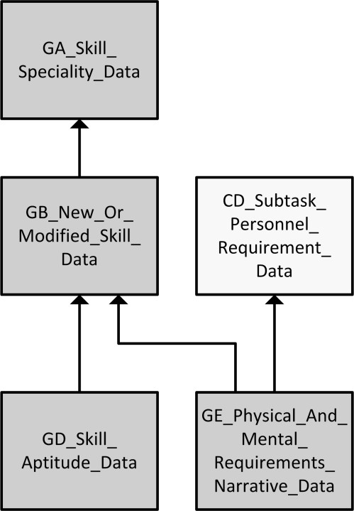
GB_New_or_Modified_Skill_data
Class Relationship Diagram
X
GB New or Modified Skill
Description
This entity contains information about new or modified skill requirements. This entity may be used to identify New or Modified Skill Additional Requirements, Educational Qualifications, Skill Justification, and Additional Training Requirements. For a given entity instance of information, the following cross-element edits apply to entity GB:
a) SSC is migrated into this entity as a non-identifying key, which means that this key is not required to uniquely identify an instance of the entity.
b) A Security Clearance is required for each New or Modified SSC.
c) Armed Services Vocational Aptitude Battery (ASVAB) Armed Forces Qualification Test (AFQT) Expected Range Low and High are required for each ASVAB AFQT Score.
d) ASVAB AFQT Lowest Percent Low and High are required for each ASVAB AFQT Score.
Child of Class
GA_Skill_Specialty_data
Key Properties
Additional Properties
armed_services_vocational_aptitude_battery_armed_forces_qualification_test_expected_range_high
armed_services_vocational_aptitude_battery_armed_forces_qualification_test_expected_range_low
armed_services_vocational_aptitude_battery_armed_forces_qualification_test_lowest_percent_high
armed_services_vocational_aptitude_battery_armed_forces_qualification_test_lowest_percent_low
armed_services_vocational_aptitude_battery_armed_forces_qualification_test_score
duty_position_requiring_a_new_or_revised_skill
new_or_modified_skill_level_code
recommended_civilian_grade
recommended_military_rank_rate
security_clearance
skill_specialty_code
test_score
new_or_modified_skill_additional_requirements_narrative
new_or_modified_skill_educational_qualifications_narrative
new_or_modified_skill_justification_narrative
new_or_modified_skill_additional_training_requirements_narrative
Class
GD_Skill_Aptitude_Data_data
Class Relationship Diagram
X
GD Skill Aptitude Data
Description
This entity contains information about Armed Services Vocational Aptitude Battery scores.
a) ASVAB Aptitude Element Expected Range Low and High are required for each ASVAB Aptitude Element.
b) ASVAB Aptitude Element Lowest Percent Low and High are required for each ASVAB Aptitude Element.
Child of Class
GB_New_or_Modified_Skill_data
Key Properties
Additional Properties
armed_services_vocational_aptitude_battery_aptitude_element_expected_range_high
armed_services_vocational_aptitude_battery_aptitude_element_expected_range_low
armed_services_vocational_aptitude_battery_aptitude_element_lowest_percent_high
armed_services_vocational_aptitude_battery_aptitude_element_lowest_percent_low
Class
GE_Physical_and_Mental_Requirements_Narrative_data
Class Relationship Diagram
X
GE Physical and Mental Requirements Narrative
Description
This entity contains information that identifies any unique physical/mental personnel attributes required or recommended as prerequisites to full qualification in the applicable task.
Child of Class
CD_Subtask_Personnel_Requirement_data
GB_New_or_Modified_Skill_data
Key Properties
Additional Properties
Class
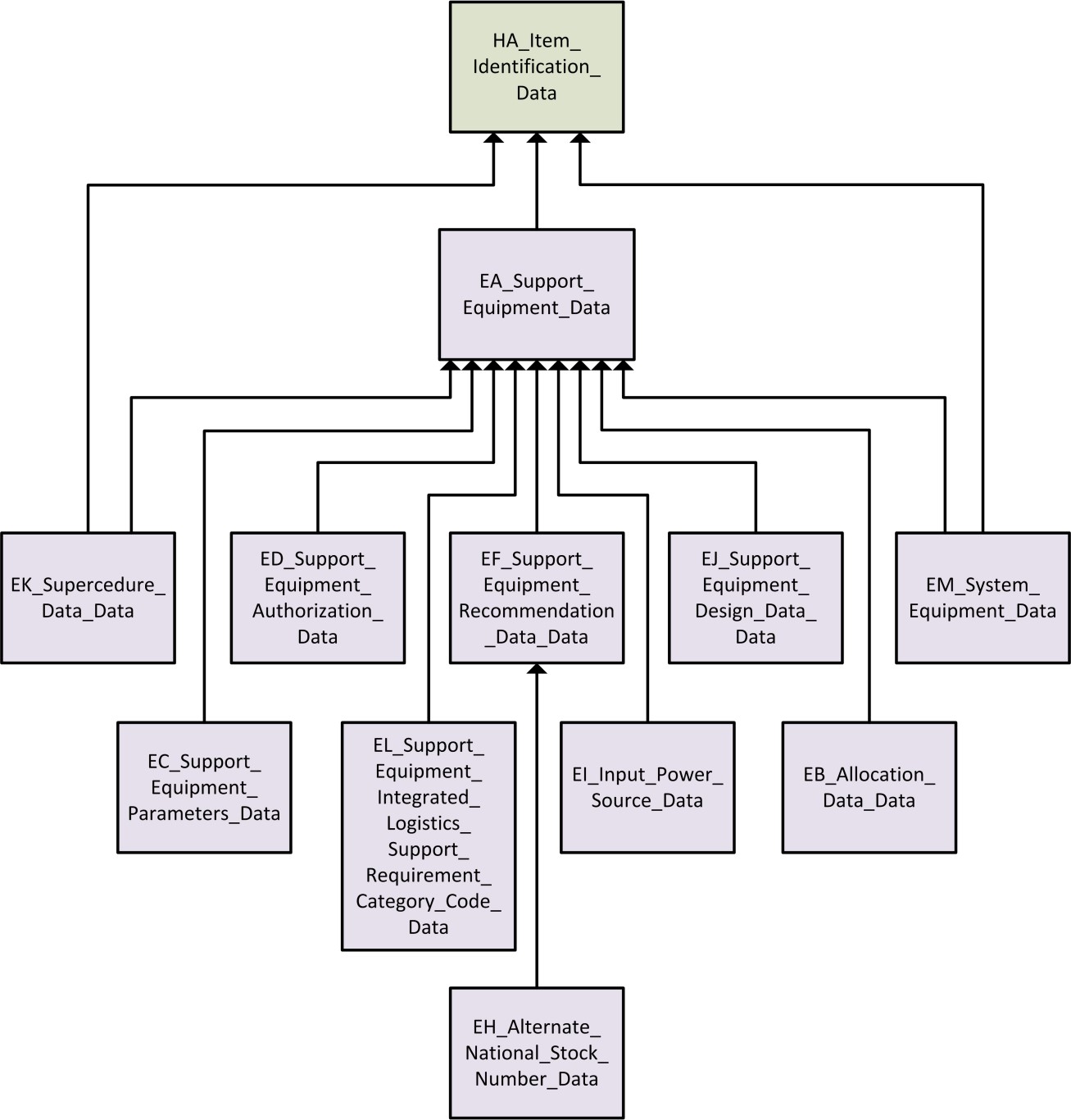
EA_Support_Equipment_data
Class Relationship Diagram
X
EA Support Equipment
Description
This entity captures a large portion of data that occurs one time per support/training equipment item. This entity is used as the foundation for support/training equipment documentation as a whole. This entity contains the support equipment narratives.
a) If Adapter/Interconnection Device Required is "Y", entities UI and UJ must be completed.
b) If entries exist for Operating Dimensions or Weight, Storage Dimensions or Weight, or Support Equipment Shipping Dimensions or Weight, their respective units of measure must have entries also.
c) Up to eight Using Service Designator Codes can be entered at one time in a continuous string. This capability allows for all possible combinations of using services to be entered.
d) Entries in any cost or price field requires a single entry in the Currency Code field. For the support equipment all price and cost data will be expressed with one currency code.
Child of Class
HA_Item_Identification_data
Key Properties
Additional Properties
acquisition_decision_office
adapter_interconnector_device_required
calibration_item
calibration_measurement_requirement_summary_recommended
calibration_required
calibration_standard
calibration_time
calibration_interval
contractor_furnished_equipment_government_furnished_equipment
custody_code
date_of_first_article_delivery
design_data_price
drawing_classification
economic_analysis
end_article_item_designator
extended_unit_price
family_group
generic_code
government_designator
hardware_development_price
integrated_logistics_support_price
life_cycle_status
life_span
logistics_control_code
logistics_decision_office
logistics_support_analysis_recommendation_code
management_plan
managing_command_agency
mobile_facility_code
modification_or_change
operating_and_support_cost
operating_dimensions_unit_of_measure
operating_height
operating_length
operating_weight
operating_weight_unit_of_measure
operating_width
operators_manual
pass_thru_price
preparing_activity
printed_circuit_board_repair_operations_maintenance_level
program_element
program_support_inventory_control_point
recurring_cost
reportable_item_control_code
revolving_assets
self_test_code
sensors_or_transducers
sketch
skill_specialty_code_for_support_equipment_operator
spare_factor
special_management_code
standard_interservice_agency_serial_control_number
storage_dimensions_unit_of_measure
storage_height
storage_length
storage_weight
storage_weight_unit_of_measure
storage_width
support_equipment_calibration_operations_maintenance_level
support_equipment_contract_number
support_equipment_full_item_name
support_equipment_grouping
support_equipment_item_category_code
support_equipment_mean_time_between_failures
support_equipment_mean_time_between_maintenance_actions
support_equipment_mean_time_to_repair
support_equipment_repair_operations_maintenance_level
support_equipment_required
support_equipment_service_designator
support_equipment_shipping_dimensions_unit_of_measure
support_equipment_shipping_height
support_equipment_shipping_length
support_equipment_shipping_weight
support_equipment_shipping_weight_unit_of_measure
support_equipment_shipping_width
support_equipment_source_maintenance_recoverability_code
technical_evaluation_priority_code
technical_manual_required_code
test_language
test_measurement_and_diagnostic_equipment_register_code
test_measurement_and_diagnostic_equipment_register_index_number
test_points
type_classfication
type_equipment_code
using_service_designator_code
year_of_fielding
support_equipment_functional_analysis_narrative
support_equipment_description_and_function_narrative
support_equipment_nonproliferation_effort_narrative
support_equipment_characteristics_narrative
support_equipment_installation_factors_or_other_facilities_narrative
support_equipment_additional_skills_and_special_training_requirements_narrative
support_equipment_explanation_narrative
support_equipment_justification_narrative
support_equipment_cost_price_currency_code
Class
EB_Allocation_Data_data
Class Relationship Diagram
X
EB Allocation Data
Description
This entity allows documenting of specific information relating allocation documents to discrete facility types and maintenance levels. Ten allowance ranges can be documented to describe the quantity of SE or Automatic Test Equipment (ATE) items necessary to support the number of end articles related to each discrete range of supported end item density. Attribute Allocation Data dictates the value of each range for the number of pieces of: (a) end items; (b) ATE items; or, (c) depot overhaul requirements that the entered quantity of SE can support.
Child of Class
EA_Support_Equipment_data
Key Properties
Additional Properties
allocation_designation_description
allocation_extended_range
allocation_land_vessel_code
allocation_maintenance_level_function
allocation_station_identification_code
allocation_range_1
allocation_range_2
allocation_range_3
allocation_range_4
allocation_range_5
allocation_range_6
allocation_range_7
allocation_range_8
allocation_range_9
allocation_range_10
Class
EC_Support_Equipment_Parameters_data
Class Relationship Diagram
X
EC Support Equipment Parameters
Description
This entity allows documenting the discrete parameters that can be measured, generated, etc., by the support/training equipment. The capabilities documented here are the basis for determining suitability of an SE item when compared to the unit under test (UUT) parameters. This entity can be used to document parameters for either Calibration Maintenance Requirements Summary (CMRS) Category II or Category III SE.
Example
Child of Class
EA_Support_Equipment_data
Key Properties
Class
ED_Support_Equipment_Authorization_data
Class Relationship Diagram
X
ED Support Equipment Authorization
Description
This entity allows documenting specific activities and quantities to which the SE item is to be authorized, as well as the location of each activity. Entity keys are SE Reference Number, SE CAGE Code, and Activity Name/Location.
Example
Child of Class
EA_Support_Equipment_data
Key Properties
Additional Properties
Class
EF_Support_Equipment_Recommendation_Data_data
Class Relationship Diagram
X
EF Support Equipment Recommendation Data
Description
This entity allows documenting SERD specific information such as, submittal and disposition dates. Entity keys are SE Reference Number, SE CAGE Code, SERD Number, and SERD Revision.
Example
Child of Class
EA_Support_Equipment_data
Key Properties
Additional Properties
Class
EH_Alternate_National_Stock_Number_data
Class Relationship Diagram
X
EH Alternate National Stock Number
Description
This entity allows documenting alternate NSNs of items that may be substituted for the subject Support/Training Equipment item. This information is used specifically by the SERD data exchange set.
Example
Child of Class
EF_Support_Equipment_Recommendation_Data_data
Key Properties
support_equipment_commercial_and_government_entity_code
support_equipment_reference_number
support_equipment_recommendation_data_number
support_equipment_recommendation_data_revision
alternate_national_stock_number_federal_supply_classification
alternate_national_stock_number_national_item_identification_number
Class
EI_Input_Power_Source_data
Class Relationship Diagram
X
EI Input Power Source
Description
This entity is utilized to document power requirements to operate the support/training equipment under analysis. Included are voltage levels, frequency ranges, power requirements, phase type, and alternating or direct current data.
a) The Source Option Number should be assigned sequentially from “1” to “99” (manually or automatically) for each unique set of power requirements for a subject piece of SE.
b) A unique set of power requirements could have only one value different from another set of power requirements.
Child of Class
EA_Support_Equipment_data
Key Properties
Additional Properties
Class
EJ_Support_Equipment_Design_Data_data
Class Relationship Diagram
X
EJ Support Equipment Design Data
Description
This entity allows documenting detailed cost, requirement, and recommendation information for the various design data elements. For the design data estimated price and associated currency code the elements must both be blank or both have entries.
Child of Class
EA_Support_Equipment_data
Key Properties
Class
EK_Supersedure_Data_data
Class Relationship Diagram
X
EK Supersedure Data
Description
This entity provides information about the item replacing, or being replaced by, the SE item under analysis. This information is normally regulated by SERD Number, but may be governed by reference number and CAGE. Entity keys are SE Reference Number, SE CAGE Code, as well as Supersedure CAGE Code and Supersedure Reference Number, which migrate from entity HA and are given the role name "Supersedure". NOTE: It is mandatory that the Supersedure Type element be completed.
Child of Class
EA_Support_Equipment_data
HA_Item_Identification_data
Key Properties
Class
EL_Support_Equipment_Integrated_Logistics_Support_Requirement_Category_Code_data
Class Relationship Diagram
X
EL Support Equipment Integrated Logistics Support Requirement Category Code
Description
This entity allows documenting the element(s) of ILS that are required or recommended to be addressed for the SE item. Also included is the estimated price, whether requiring authority required or performing activity recommended, and a scope (normally a data item description) for each ILS element documented. The integrated logistics support estimated price and currency code fields must either both be blank, or both have entries.
Child of Class
EA_Support_Equipment_data
Key Properties
Additional Properties
integrated_logistics_support_requirement_category_code_contractor_recommended
integrated_logistics_support_requirement_category_code_estimated_price
integrated_logistics_support_requirement_category_code_estimated_price_currency_code
integrated_logistics_support_requirement_category_code_government_required
integrated_logistics_support_requirement_category_code_scope
Class
EM_System_Equipment_data
Class Relationship Diagram
X
EM System Equipment
Description
This entity allows documenting items that are components of the system/equipment and are necessary to be used in conjunction with the SE item to perform its intended function. For example, a wiring harness with the same part number as the one used on the system/equipment might be required at a test bench in order to fault isolate a line replaceable unit (LRU). This wiring harness would be considered a required piece of system equipment. Entity Keys include System CAGE and System Reference Number (both migrate from entity HA, but are given "System" role name), and SE CAGE Code and SE Reference Number (migrate from entity EA).
Child of Class
EA_Support_Equipment_data
HA_Item_Identification_data
Key Properties
Additional Properties
Class
UA_Article_Requiring_Support_Unit_Under_Test_data
Class Relationship Diagram
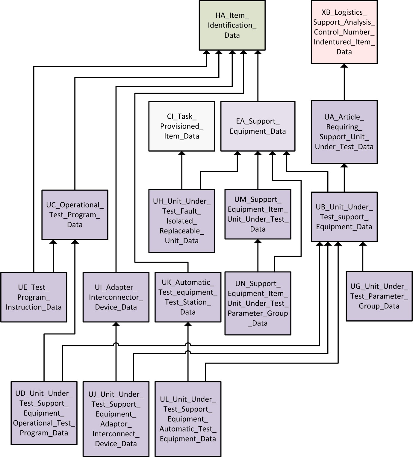
X
UA Article Requiring Support Unit Under Test
Description
This entity identifies the UUT that is a component of a system breakdown structure. A UUT can be either a component of the system/equipment or a piece of complex Support Equipment itself that must be documented under the end article for contractual or provisioning purposes. Entity keys are migrated from entity XB, but are given the role name "UUT" to distinguish them. The EIAC must be the same as in entity XB, therefore it, is not role named.
Child of Class
XB_Logistics_Support_Analysis_Control_Number_Indentured_Item_data
Key Properties
Class
UB_Unit_Under_Test_Support_Equipment_data
Class Relationship Diagram
X
UB Unit Under Test Support Equipment
Description
This entity serves as the tie-in between the Support Equipment and the Unit under Test. Keys are migrated into entity UB from the EA and UA Entities.
Example
Child of Class
EA_Support_Equipment_data
UA_Article_Requiring_Support_Unit_Under_Test_data
Key Properties
end_item_acronym_code
unit_under_test_logistics_support_analysis_control_number
unit_under_test_alternate_logistics_support_analysis_control_number_code
unit_under_test_logistics_support_analysis_control_number_type
support_equipment_commercial_and_government_entity_code
support_equipment_reference_number
Class
UC_Operational_Test_Program_data
Class Relationship Diagram
X
UC Operational Test Program
Description
This entity allows documenting identification and cost data pertaining to the Operational Test Program (OTP). The OTP is used in conjunction with another support equipment item, normally ATE. This entity provides supporting information to the UD entity. Keys are migrated from the HA entity and given the role name "OTP" to distinguish them. The Currency Code is required if either cost attribute is non-blank.
Child of Class
HA_Item_Identification_data
Key Properties
Additional Properties
operational_test_program_apportioned_unit_cost_nonrecurring
operational_test_program_apportioned_unit_cost_recurring
operational_test_program_apportioned_unit_cost_nonrecurring_recurring_currency_code
operational_test_program_coordinated_test_plan
operational_test_program_standards_for_comparison
operational_test_program_support_equipment_recommendation_data_number
Class
UD_Unit_Under_Test_Support_Equipment_Operational_Test_Program_data
Class Relationship Diagram
X
UD Unit Under Test Support Equipment Operational Test Program
Description
This entity ties together the relationship between the SE, UUT, and the OTP to maintain the specific application of the OTP. Entity keys are EIAC, UUT LCN, UUT ALC, UUT LCN Type, SE Reference Number, SE CAGE Code (these migrate from the UB entity), and OTP Reference Number and OTP CAGE Code, which migrate from the UC entity.
Child of Class
UB_Unit_Under_Test_Support_Equipment_data
UC_Operational_Test_Program_data
Key Properties
end_item_acronym_code
unit_under_test_logistics_support_analysis_control_number
unit_under_test_alternate_logistics_support_analysis_control_number_code
unit_under_test_logistics_support_analysis_control_number_type
support_equipment_commercial_and_government_entity_code
support_equipment_reference_number
operational_test_program_commercial_and_government_entity_code
operational_test_program_reference_number
Class
UE_Test_Program_Instruction_data
Class Relationship Diagram
X
UE Test Program Instruction
Description
This entity allows documenting basic identification and cost information pertaining to a Test Program Instruction (TPI). The TPI is used as an aid in the use of an OTP. Entity keys are migrated from the HA entity and given the role name "TPI" to form the following keys: TPI Reference Number and TPI CAGE Code. Also, the keys from entity UC (OTP CAGE and Reference Number) are migrated in as foreign keys. The Currency Code is required if either cost attribute is non-blank.
Child of Class
HA_Item_Identification_data
UC_Operational_Test_Program_data
Key Properties
Additional Properties
test_program_instruction_apportioned_unit_cost_nonrecurring
test_program_instruction_apportioned_unit_cost_recurring
test_program_instruction_apportioned_unit_cost_nonrecurring_recurring_currency_code
test_program_instruction_self_test
test_program_instruction_support_equipment_recommendation_data_number
test_program_instruction_technical_data_package
Class
UG_Unit_Under_Test_Parameter_Group_data
Class Relationship Diagram
X
UG Unit Under Test Parameter Group
Description
This entity allows documenting specific information about individual parameters that the Unit Under Test requires to have measured, generated, etc. by the support equipment. This entity is used when the UUT is a sub-element of the system/equipment (CMRS category I item), as opposed to being another piece of support equipment, with one exception. This entity can be used to document parameters for a piece of complex SE that is an LSA candidate, thereby, making it the UUT. NOTE: The UUT Parameter Grouping Code and the SE Parameter Grouping Code (entity EC) provide the common link between the parameters that need to be tested by the UUT and the parameters that the piece of SE can test.
Example
Child of Class
UB_Unit_Under_Test_Support_Equipment_data
Key Properties
end_item_acronym_code
unit_under_test_logistics_support_analysis_control_number
unit_under_test_alternate_logistics_support_analysis_control_number_code
unit_under_test_logistics_support_analysis_control_number_type
support_equipment_commercial_and_government_entity_code
support_equipment_reference_number
unit_under_test_parameter_group_code
Additional Properties
unit_under_test_calibration_measurement_requirement_summary_parameter_code
unit_under_test_parameter
unit_under_test_parameter_accuracy
unit_under_test_parameter_input_output_code
unit_under_test_parameter_operational_specification_code
unit_under_test_parameter_range_from
unit_under_test_parameter_range_to
unit_under_test_parameter_range_value_code
unit_under_test_parameter_test_accuracy_ratio_actual
unit_under_test_parameter_test_accuracy_ratio_desired
Class
UH_Unit_Under_Test_Fault_Isolated_Replaceable_Unit_data
Class Relationship Diagram
X
UH Unit Under Test Fault Isolated Replaceable Unit
Description
This entity allows documenting the relationship between SE, UUT, task provisioned items, and Fault Isolated Replaceable Units (FIRU). The FIRU is an item that is subordinate to the UUT LCN and the Task LCN in hardware breakdown. In fact, the UUT LCN and the Task LCN are one and the same and therefore, must be identical to each other. This entity also allows documenting the percentage of faults that can be isolated to a given ambiguity group (up to two groups) and its respective number of items per ambiguity group. Entity keys include those that originate in entity CI and are migrated to entity UH. Keys from entity EA migrate down as nonidentifying.
Child of Class
CI_Task_Provisioned_Item_data
EA_Support_Equipment_data
Key Properties
end_item_acronym_code
task_logistics_support_analysis_control_number
task_alternate_logistics_support_analysis_control_number_code
task_logistics_support_analysis_control_number_type
task_provision_task_code
task_provision_logistics_support_analysis_control_number
task_provision_alternate_logistics_support_analysis_control_number_code
task_provision_logistics_support_analysis_control_number_type
task_provision_commercial_and_government_entity_code
task_provision_reference_number
Additional Properties
unit_under_test_fault_isolated_replaceable_unit_ambiguity_group_1
unit_under_test_fault_isolated_replaceable_unit_ambiguity_group_2
unit_under_test_fault_isolated_replaceable_unit_percent_failure_1
unit_under_test_fault_isolated_replaceable_unit_percent_failure_2
unit_under_test_fault_isolated_replaceable_unit_test_requirements_document_indicator
support_equipment_commercial_and_government_entity_code
support_equipment_reference_number
Class
UI_Adapter_Interconnector_Device_data
Class Relationship Diagram
X
UI Adapter Interconnector Device
Description
This entity contains pricing and identification information about items that are utilized to interface the UUT with the SE. The entity keys are migrated from entity HA and given the role names Adapter Interconnector Device (AID) Reference Number and AID CAGE Code. The Currency Code is required if either cost attribute is non-blank.
Example
Child of Class
HA_Item_Identification_data
Key Properties
Additional Properties
adapter_interconnector_device_apportioned_unit_cost_nonrecurring
adapter_interconnector_device_apportioned_unit_cost_recurring
adapter_interconnector_device_apportioned_unit_cost_nonrecurring_recurring_currency_code
adapter_interconnector_device_common_unit_under_test
adapter_interconnector_device_support_equipment_recommendation_data_number
Class
UJ_Unit_Under_Test_Support_Equipment_Adapter_Interconnector_Device_ data.
Class Relationship Diagram
X
UJ Unit Under Test Support Equipment Adapter Interconnector Device data.
Description
This entity cross-references data pertaining to the relationship between the SE, AID, and the UUT. Entity keys include the CAGE and Reference Number from entity UI and the keys migrated from entity UB, SE Reference Number, and SE CAGE Code.
Child of Class
UB_Unit_Under_Test_Support_Equipment_data
UI_Adapter_Interconnector_Device_data
Key Properties
end_item_acronym_code
unit_under_test_logistics_support_analysis_control_number
unit_under_test_alternate_logistics_support_analysis_control_number_code
unit_under_test_logistics_support_analysis_control_number_type
support_equipment_commercial_and_government_entity_code
support_equipment_reference_number
adapter_interconnector_device_commercial_and_government_entity_code
adapter_interconnector_device_reference_number
Class
UK_Automatic_Test_Equipment_Test_Station_data
Class Relationship Diagram
X
UK Automatic Test Equipment Test Station
Description
This entity is used to document identification and government designator information concerning the Automatic Test Equipment (ATE) Test Station required on a SERD summary. Entity keys are migrated from entity HA and given role names of ATE Reference Number and ATE CAGE Code.
Child of Class
HA_Item_Identification_data
Key Properties
Additional Properties
Class
UL_Unit_Under_Test_Support_Equipment_Automatic_Test_Equipment_data
Class Relationship Diagram
X
UL Unit Under Test Support Equipment Automatic Test Equipment
Description
This entity cross-references the ATE Test Station (entity UK) data with the UUT SE (entity UB). Entity keys are ATE Reference Number and ATE CAGE Code migrated from entity UK and the keys migrated from entity UB, SE Reference Number, and SE CAGE Code.
Child of Class
UB_Unit_Under_Test_Support_Equipment_data
UK_Automatic_Test_Equipment_Test_Station_data
Key Properties
end_item_acronym_code
unit_under_test_logistics_support_analysis_control_number
unit_under_test_alternate_logistics_support_analysis_control_number_code
unit_under_test_logistics_support_analysis_control_number_type
support_equipment_commercial_and_government_entity_code
support_equipment_reference_number
automatic_test_equipment_commercial_and_government_entity_code
automatic_test_equipment_reference_number
Class
UM_Support_Equipment_Item_Unit_Under_Test_data
Class Relationship Diagram
X
UM Support Equipment Item Unit Under Test
Description
This entity identifies pieces of SE (Calibration and Measurement Requirement Summary (CMRS) category II items) that are linked with CMRS category III items (SE in support of the category II SE). Normally, Entities UM and UN are only used if a CMRS is required on contract. Entity keys are migrated down from the EA entity (Support Equipment) and given a role name of Support Equipment Unit Under Test to distinguish them.
Child of Class
EA_Support_Equipment_data
Key Properties
Additional Properties
support_equipment_unit_under_test_allowance
support_equipment_unit_under_test_calibrations_measurement_requirements_summary_status
support_equipment_unit_under_test_maintenance_plan_number
support_equipment_unit_under_test_test_requirements_document_number
support_equipment_unit_under_test_work_package_reference
Class
UN_Support_Equipment_Unit_Under_Test_Parameter_Group_data
Class Relationship Diagram
X
UN Support Equipment Unit Under Test Parameter Group
Description
This entity allows documenting specific information about individual parameters that a piece of SE (CMRS category II) requires to have calibrated, measured, etc., by another piece of SE (CMRS category III item). Data from this entity will be used on the CMRS report. Entity keys include the SE UUT Parameter Group Code, keys migrated from entity EA and given role names of "Testing", and keys from entity UM. NOTE: The SE UUT Parameter Grouping Code and the SE Parameter Grouping Code (entity EC) provide the link between the parameters of CMRS category III items and category II items, respectively.
Child of Class
UM_Support_Equipment_Item_Unit_Under_Test_data
Key Properties
Additional Properties
support_equipment_unit_under_test_calibrations_measurement_requirements_summary_parameter_code
support_equipment_unit_under_test_parameter
support_equipment_unit_under_test_parameter_accuracy
support_equipment_unit_under_test_parameter_input_output_code
support_equipment_unit_under_test_parameter_range_from
support_equipment_unit_under_test_parameter_range_to
support_equipment_unit_under_test_parameter_range_value_code
support_equipment_unit_under_test_parameter_test_accuracy_ratio_actual
support_equipment_unit_under_test_parameter_test_accuracy_ratio_desired
Class
FA_Facility_data
Class Relationship Diagram
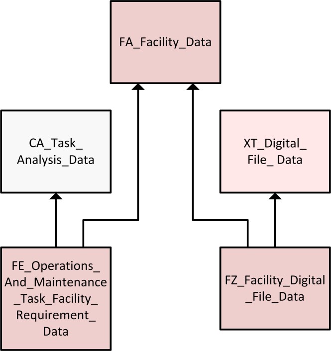
X
FA Facility
Description
This entity identifies the facility by Name, Category Code, and Type that the system/equipment under analysis requires. Narratives may be used to identify Facility Capability, and Facility Location of either the baseline facility or the new or modified facility. Narratives may be used to identify Facility Maintenance Requirements, Facility Requirements for Operations, Facility Training Requirement, Facility Requirements Special Considerations, and Facility Requirements Supply and Storage for a baseline facility. Baseline is describing the requirements needed for a facility; this applies to both an existing facility and a new or modified facility. This entity contains information about modifications of existing facilities or requirements for new facilities. This entity may be used to identify Facility Design Criteria, Facility Installation Lead Time, Facility Task Area Breakdown, Facility Utilization, Facility Requirements, Facility Unit Cost Rationale, Facility Justification, Type of Construction, and Utilities Requirement. For a given entity instance of information, the following apply to entity FA:
a) Facility Area and Facility Area Unit of Measure (UM) must either both be blank, or both have entries.
b) Facility Construction UM Price and Construction UM must either both be blank, or both have entries.
c) The Facility Construction Price and Currency Code fields must either both be blank or both have entries.
Key Properties
Additional Properties
construction_unit_of_measure
facility_area
facility_area_unit_of_measure
facility_class
facility_construction_unit_of_measure_price
facility_construction_unit_of_measure_price_currency_code
facility_drawing_classification
facility_drawing_number
facility_drawing_revision
facility_capability_narrative
facility_location_narrative
baseline_facility_maintenance_requirement_narrative
baseline_facility_requirements_for_operations_narrative
baseline_facility_requirements_for_training_narrative
baseline_facility_requirements_special_considerations_narrative
baseline_facility_requirements_supply_storage_narrative
new_or_modified_facility_design_criteria_narrative
new_or_modified_facility_installation_lead_time_narrative
new_or_modified_facility_task_area_breakdown_narrative
new_or_modified_facility_utilization_narrative
new_or_modified_facility_requirements_narrative
new_or_modified_facility_unit_cost_rationale_narrative
new_or_modified_facility_justification_narrative
new_or_modified_facility_type_of_construction_narrative
new_or_modified_facility_utilities_requirement_narrative
Class
FE_Operations_and_Maintenance_Task_Facility_Requirement_data
Class Relationship Diagram
X
FE Operations and Maintenance Task Facility Requirement
Description
This entity identifies a need for operations/maintenance facilities for a given task.
Child of Class
CA_Task_Requirement_data
FA_Facility_data
Class
FZ_Facility_Digital_File_data
Class Relationship Diagram
X
FZ Facility Digital File
Description
This entity contains elements to associate or map a document, image, or other electronic medium to a facility.
Child of Class
FA_Facility_data
XT_Digital_File_data
Class
JA_Transportation_data
Class Relationship Diagram
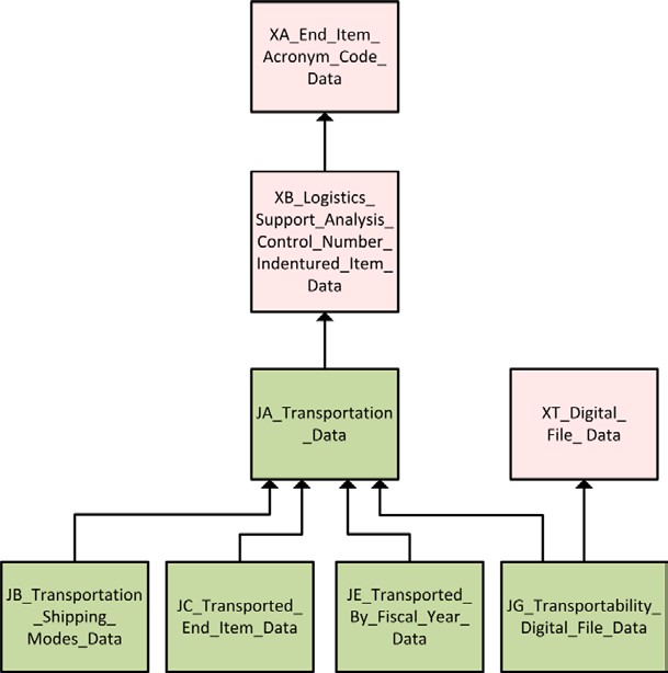
X
JA Transportation
Description
This entity identifies the transportation characteristics of the system/equipment under analysis. This entity may be used to identify Transportation Shock and Vibration Requirements, Lifting and Tiedown Remarks, Projection Characteristics, Regulatory Requirements, Special Services and Equipment, Sectionalized Remarks, Transportation Remarks, Transport To/From Remarks, Environmental Considerations, Military Distance Classification, Unusual and Special Requirements, Venting and Protective Clothing, and Disaster Response Force. It describes what is required for the system/equipment to be transported. For a given row of information, the following cross-element edits apply to entity JA:
a) The transportability area can only be used if an item has been identified by a Sectionalized Item Transportation Indicator entity XB, or by a Transportation End Item Indicator entity XC.
b) If the system/equipment is being sectionalized for transportation, then a Sectionalized Identification should be filled out.
c) If the system/equipment has environmental considerations, a “Y”should be entered in the Environmental Handling and Transportation Indicator.
Child of Class
XB_Logistics_Support_Analysis_Control_Number_Indentured_Item_data
Key Properties
Additional Properties
cargo_tiedown_narrative
delivery_schedule
environmental_handling_and_transportation_indicator
military_unit_type
net_explosive_weight
nonoperational_fragility_factor
proper_shipping_name
revision_date
sectionalized_identification
speed
theater_of_operation
towing_speed
transportation_contract_number
transportation_indicator
transportation_shock_vibration_remarks_narrative
transportation_lifting_and_tiedown_remarks_narrative
transportation_projection_remarks_narrative
transportation_regulatory_requirements_narrative
transportation_remarks_narrative
transportation_special_service_and_equipment_narrative
transportation_sectionalized_remarks_narrative
transportation_transport_to_and_from_narrative
transportation_environmental_considerations_narrative
transportation_military_distance_classification_narrative
transportation_unusual_and_special_requirements_narrative
transportation_venting_and_protective_clothing_narrative
transportation_disaster_response_force_narrative
Class
JB_Transportation_Shipping_Modes_data
Class Relationship Diagram
X
JB Transportation Shipping Modes
Description
This entity identifies the different possible transportation shipping modes for the system/equipment under analysis. This entity can identify the different types of aircraft and whether the aircraft will transport the item under analysis externally or internally. This entity can identify the different type of helicopters, their mission capabilities, and whether the helicopter will transport the item under analysis externally or internally. This entity can identify the highway prime and alternate model types and what type of payload capacity the transporter has. This entity can identify the type of lighterages and whether the item under analysis can be stowed on deck. This entity can identify the type of rail system that will be used and which countries the rail system will run through for the item under analysis. This entity can identify the type of ships and whether the item under analysis can be stowed on deck. For a given entity instance of information, the following cross-element edits apply to entity JB:
a) This entity can only be used if an ”S” or “B” has been entered in the Transportation Indicator entity JA.
b) Transportation Item Designator and External or Internal Load Indicator should only be used when the Transportation Character Mode Type of ”A” for an aircraft is entered.
c) External or Internal Load Indicator and Transportation Item Designator for an aircraft must either both be blank, or both have entries.
d) Transportation Item Designator, Helicopter Mission Altitude, Helicopter Mission Distance, Helicopter Mission Payload, Helicopter Mission Temperature, Helicopter Mission Time, and External or Internal Load Indicator should only be filled out when the Transportation Character Mode Type of ”B” for a helicopter is entered.
e) External or Internal Load Indicator and Transportation Item Designator for a helicopter must either both be blank, or both have entries.
f) Highway Prime Load, Highway Prime Model Type, Highway Alternate Load, and Highway Alternate Model Type should only be filled out when the Transportation Character Mode Type of ”C” is entered.
g) Highway Prime Model Load and Highway Prime Model Type must either both be blank, or both have entries.
h) Highway Alternate Model Load and Highway Alternate Model Type must either both be blank, or both have entries.
i) Sea Deck Stowage and Transportation Item Designator and should only be filled out when the Transportation Character Mode Type of ”D” for a lighterage is entered.
j) Sea Deck Stowage and Transportation Item Designator must either both be blank, or both have entries.
k) Transportation Item Designator, Rail Use and Rail Transportation Country should only be filled out when the Transportation Character Mode Type of ”E” is entered.
l) Rail Use and Rail Transportation Country must either both be blank, or both have entries.
m) Sea Deck Stowage and Transportation Item Designator should only be filled out when the Transportation Character Mode Type of ”F” for a ship is entered.
n) Sea Deck Stowage and Transportation Item Designator must either both be blank, or both have entries.
o) Container Length and Container Type must either both be blank, or both have entries.
Example
Child of Class
JA_Transportation_data
Key Properties
Additional Properties
container_length
container_type
electrical_grounding_narrative
external_or_internal_load_indicator
freight_classification
helicopter_mission_altitude
helicopter_mission_distance
helicopter_mission_payload
helicopter_mission_temperature
helicopter_mission_time
highway_alternate_model_load
highway_alternate_model_type
highway_prime_model_load
highway_prime_model_type
highway_transportation_type
rail_transportation_country
rail_use
sea_deck_stowage
shipping_configuration
transportation_item_designator
Class
JC_Transported_End_Item_data
Class Relationship Diagram
X
JC Transported End Item
Description
This entity provides information pertaining to a system/EI that is to be transported. This entity may be used to identify Tire Requirements, Skid Remarks, Tracked Wheeled Remarks, Turning Information, Axle and Suspension Remarks, and Other Transported Equipment. For a given entity instance of information, the following cross- element edits apply to entity JC:
a) This entity can only be used if an ”E” or “B” has been entered in the Transportation Indicator entity JA.
b) Operational Weight Empty and Military Load Classification Empty must either both be blank, or both have entries.
c) Operational Weight Loaded and Military Load Classification Loaded must either both be blank, or both have entries.
d) Skid Number of Skids, Skid Area, and Skid Area UM should only be used when the Mobility Type of ”A” is entered.
e) Skid Area and Skid Area UM must either both be blank, or both have entries.
f) Tracked Ground Pressure, Tracked Road Wheel Weight, Tracked Pads Touching, Tracked Pad Shoe Area, and Tracked Pad Shoe Area UM should only be used when the Mobility Type of ”B” is entered. Wheeled Inflation Pressure, Wheeled Number of Tires, Wheeled Tire Load Ratings, Wheeled Tire Size, and Wheeled Weight Ratings may also apply to tracked vehicles.
g) Tracked Pad Shoe Area and Tracked Pad Shoe Area UM must either both be blank, or both have entries.
h) Wheeled Inflation Pressure, Wheeled Number of Tires, Wheeled Tire Load Ratings, Wheeled Tire Size, and Wheeled Weight Ratings should be used when the Mobility Type of ”C” is entered.
Child of Class
JA_Transportation_data
Key Properties
Additional Properties
crest_angle
length_front_inside
length_front_outside
length_rear_inside
length_rear_outside
military_load_classification_empty
military_load_classification_loaded
number_of_skids
operational_weight_empty
operational_weight_loaded
shipping_weight_empty
shipping_weight_loaded
skid_area
skid_area_unit_of_measure
tracked_ground_pressure
tracked_pad_shoe_area
tracked_pad_shoe_area_unit_of_measure
tracked_pads_touching
tracked_road_wheel_weight
wheeled_inflation_pressure
wheeled_number_of_plies
wheeled_number_tires
wheeled_tire_load_ratings
wheeled_tire_size
wheeled_weight_ratings
transported_end_item_wheeled_tire_requirements_narrative
transported_end_item_skid_remarks_narrative
transported_end_item_turning_information_narrative
transported_end_item_wheeled_axle_and_suspension_remarks_narrative
transported_end_item_transported_other_equipment_narrative
Class
JE_Transport_by_Fiscal_Year_data
Class Relationship Diagram
X
JE Transport by Fiscal Year
Description
This entity contains information about the system/equipment procurement and delivery schedule.
Child of Class
JA_Transportation_data
Key Properties
Class
JG_Transportability_Digital_File_data
Class Relationship Diagram
X
JG Transportability Digital File
Description
This entity contains elements to associate or map a document, image, or other electronic medium to the transported end item.
Child of Class
JA_Transportation_data
XT_Digital_File_data
Class
HA_Item_Identification_data
Class Relationship Diagram
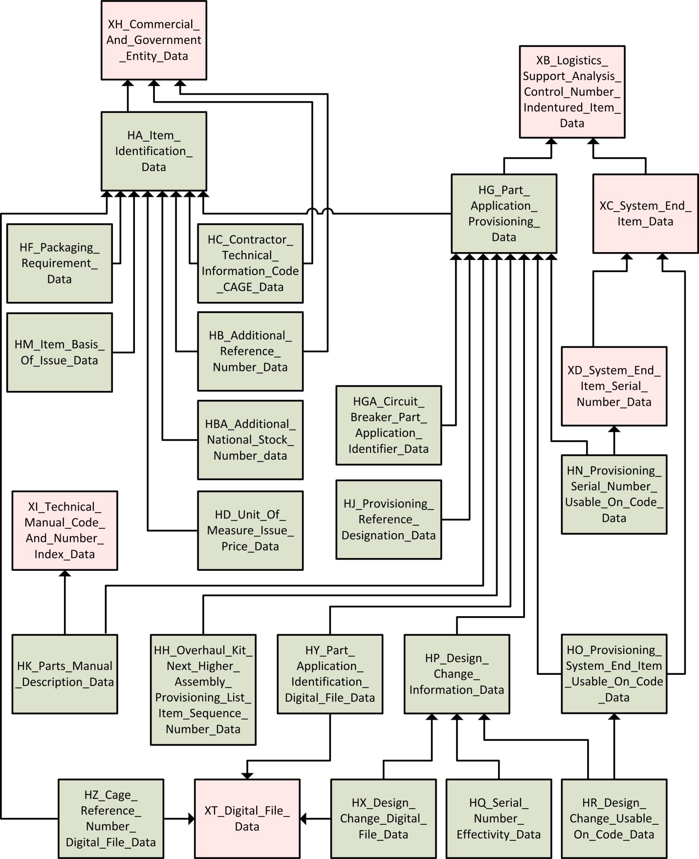
X
HA Item Identification
Description
This entity contains parts information that is not dependent of the part application such as item identification, cataloging, common maintenance information, special management characteristics, and units of measure and issue.
a) Acquisition Method Suffix Code is not allowed without Acquisition Method Code.
b) Shelf Life Action Code is not allowed without Shelf Life.
c) National Item Identification Number is not allowed without Federal Supply Classification.
d) Unit Length, Width, and Height must either be all blank or all have entries.
e) If UM equals Unit of Issue (UI), UI Conversion Factor must equal "00001".
f) The Unit of Issue “AY” for “Assembly” is a collection of parts assembled to form a complete unit, constituting a single item of supply, e.g., hose assembly. Use only when the term “assembly” is a part of the item name.
g) If Special Material Content Code is "E", then the Precious Metals Indicator Code cannot be "A".
h) Material Leadtime and Material Weight are not allowed without Industrial Materials Analysis of Capacity.
i) Currency Code required if one or more of the hazardous waste costs are non-blank.
Child of Class
XH_Commercial_and_Government_Entity_data
Key Properties
Additional Properties
acquisition_method_code
acquisition_method_suffix_code
authorization_stock_list
automatic_data_processing_equipment_code
common_and_bulk_item_list
contractor_technical_information_code
critical_item_code
criticality_code
circuit_breaker_type
defense_logistics_information_service_screening_requirement_code
demilitarization_code
document_availability_code
document_identifier_code
government_furnished_item_list
hazardous_code
hazardous_materials_storage_cost
hazardous_waste_disposal_cost
hazardous_waste_storage_cost
hazardous_waste_cost_currency_code
industrial_materials_analysis_of_capacity
item_class_of_supply
item_management_code
item_name
item_name_code
item_subclass
installation_and_checkout_item_list
interim_released_item_list
interim_support_item_list
long_lead_time_item_list
line_item_number
material
material_leadtime
material_weight
national_stock_number_activity_code
national_stock_number_cognizance_code
national_stock_number_federal_supply_classification
national_stock_number_materiel_control_code
national_stock_number_national_item_identification_number
national_stock_number_special_materiel_identification_code_materiel_management_aggregation_code
physical_security_pilferage_code
precious_metal_indicator_code
prescribed_load_list_item_list
production_lead_time
program_parts_selection_list
recommended_buy_list_item_list
reference_number_category_code
reference_number_variation_code
repairable_item_list
schedule_b_export_code
shelf_life
shelf_life_action_code
spares_acquisition_integrated_with_production
special_maintenance_item_code
special_material_content_code
system_support_package_component_list
tools_and_test_equipment_list
unit_of_issue
unit_of_issue_conversion_factor
unit_of_measure
unit_size_height
unit_size_length
unit_size_width
unit_weight
Class
HB_Additional_Reference_Number_data
Class Relationship Diagram
X
HB Additional Reference Number
Description
This entity contains Additional Reference Numbers (ARN) that may be used to identify the item of supply. Entity keys include item Reference Number and CAGE from entity HA, additional CAGE from entity XH, and ARN. In a given entity instance, when the ARN and CAGE match the primary Reference Number and CAGE, there must be an entry in Reference Number Category Code (RNCC) and this entry must be different from the RNCC entry in entity HA.
Example
Child of Class
HA_Item_Identification_data
XH_Commercial_and_Government_Entity_data
Key Properties
Class
HBA_Additional_National_Stock_Number_data
Class Relationship Diagram
X
HBA Additional National Stock Number
Description
This entity contains additional national stock numbers associated with the prime reference number identified by entity HA. The initial or primary national stock number must be documented in HA with additional national stock numbers documented in this entity. If the prime reference number in HA is a specification number that has definitive associated reference numbers for each national stock number then the reference number and CAGE fields should be completed for each national stock number.
Child of Class
HA_Item_Identification_data
Key Properties
Additional Properties
national_stock_number_activity_code
national_stock_number_cognizance_code
national_stock_number_materiel_control_code
national_stock_number_special_materiel_identification_code_materiel_management_aggregation_code
national_stock_number_commercial_and_government_entity_code
national_stock_number_reference_number
national_stock_number_reference_number_variation_code
national_stock_number_reference_number_category_code
justification
Class
HC_Contractor_Technical_Information_Code_CAGE_data
Class Relationship Diagram
X
HC Contractor Technical Information Code CAGE
Description
This entity contains contractor technical information code (CTIC) CAGEs. Entity keys include: Item Reference Number, and CAGE, from entity HA, and CTIC CAGE from entity XH. CTIC must be established in Entity HA with values of either "-K", "-M", or "-N" for the Reference Number and CAGE combination, prior to establishing a value in this entity.
Child of Class
HA_Item_Identification_data
XH_Commercial_and_Government_Entity_data
Class
HD_Item_Unit_of_Measure_Issue_Price_data
Class Relationship Diagram
X
HD Item Unit of Measure Issue Price
Description
This entity contains UM/UI prices and associated information about the UM/UI price.
a) UM/UI must be established in entity HA for the Reference Number and CAGE combination prior to establishing a value in this entity.
b) The “price type selection” is coded “issue” for Unit of Issue price and “measure” for Unit of Measure price.
c) Multiple prices can exist for a given CAGE/Reference Number combination. For reporting purposes, the one with a "Y" in the “price provisioning” code will be the price output on a report.
d) Lot Quantity From must be less than or equal to Lot Quantity To in any entity instance.
e) Currency Code is a mandatory field.
Child of Class
HA_Item_Identification_data
Key Properties
Class
HF_Item_Packaging_Requirement_data
Class Relationship Diagram
X
HF Item Packaging Requirement
Description
This entity contains packaging data, as specified by MIL-STD-2073-1.
a) Maximum Unit Pack Length, Width, and Depth must either all be blank or all have entries for a row of information.
b) Maximum Unit Pack entries must be greater than or equal to Unit Size entries in entity HA.
c) For numeric entry, Maximum Unit Pack Weight must be greater than or equal to Unit Weight.
d) Packaging data preparer CAGE is a non-identifying key migrating from entity XH.
e) When packaging in accordance with Special Packaging Instruction (SPI), enter code “ZZ” in the Method of Preservation Code and omit entries in the following fields: Cleaning and Drying Procedures, Preservation Material Code, Wrapping Material, Cushioning and Dunnage Material, Cushioning Thickness, and Unit Container.
f) The Container National Stock Number is only the 4th-16th position of National Stock Number and Related Data.
Example
Child of Class
HA_Item_Identification_data
Key Properties
Additional Properties
cleaning_and_drying_procedures
container_national_stock_number
cushioning_and_dunnage_material
cushioning_thickness
intermediate_container_code
intermediate_container_quantity
maximum_unit_pack_cube
maximum_unit_pack_depth
maximum_unit_pack_length
maximum_unit_pack_weight
maximum_unit_pack_width
method_of_preservation_code
military_packing_code
minimal_packing_code
optional_procedures_indicator
packaging_category_code
packaging_data_preparer_commercial_and_government_entity
preservation_material_code
quantity_per_unit_pack
special_marking_code
special_packaging_instruction_number
special_packaging_instruction_number_julian_date
special_packaging_instruction_number_revision
supplemental_packaging_data
unit_container_code
unit_container_level
wrapping_material
Class
HG_Part_Application_Provisioning_data
Class Relationship Diagram
X
HG Part Application Provisioning
Description
This entity contains parts related information pertaining to the part in a specific hardware application.
a) LCN Type must always be "P" (Physical).
b) Maintenance Action Code is not allowed without Maximum Allowable Operating Time.
c) The sum of the Maintenance Task Distribution elements must always total to 100 percent.
d) The sum of the Replacement Task Distribution elements must always total to 100 percent.
e) Same as PLISN must be contained in this entity as a PLISN having an identical PCCN. The same as PLISN must be the lowest (EBCDIC value) PLISN in the entity for the same Reference Number, CAGE, and PCCN combinations (without an associated "D" Type of Change Code (TOCC)).
f) Repair Cycle Time for each Operations/Maintenance (O/M) Level (identified by the first position of the short name) must be either blank or greater for each higher O/M level. The O/M levels in ascending order are “O”, “F”,“H”, “L”, “D”, and “CON” (contractor). When numeric, the Quantity Per End Item must be greater than or equal to the Quantity Per Assembly.
g) When numeric, the Quantity Per End Item must be greater than or equal to the Quantity per Assembly.
h) The Quantity Per End Item calculation option is the same for every item in the Provisioning Contract Control Number. The Quantity Per End Item calculation option code is selected on the Entity: XC_System_End_Item_data.
i) Maintenance Task Distribution (MTD) and Replacement Task Distribution.
1) The Organizational Maintenance Task Distribution must be less than or equal to Organizational Replacement Task Distribution.
2) The Organizational Maintenance Task Distribution and Intermediate/Direct Support Maintenance Task Distribution must be less than or equal to Organizational Replacement Task Distribution and Intermediate/Direct Support Replacement Task Distribution.
3) The Organizational Maintenance Task Distribution, Intermediate/Direct Support Maintenance Task Distribution, and the Intermediate/General Support Maintenance Task Distribution must be less than or equal to the Organization Replacement Task Distribution, the Intermediate/Direct Support Replacement Task Distribution, and the Intermediate/General Support Replacement Task Distribution.
4) The Organizational Maintenance Task Distribution, Intermediate/Direct Support Maintenance Task Distribution, the Intermediate/General Support Maintenance Task Distribution , and the Special Repair Activity Maintenance Task distribution must be less than or equal to the Organization Replacement Task Distribution, the Intermediate/Direct Support Replacement Task Distribution, the Intermediate/General Support Replacement Task Distribution, and the Special Repair Acitivity Replacement Task Distribution.
5) The Organizational Maintenance Task Distribution, Intermediate/Direct Support Maintenance Task Distribution, the Intermediate/General Support Maintenance Task Distribution Maintenance Task Distribution, the Special Repair Activity Maintenance Task Distribution, and Depot/Shipyard Maintenance Task Distribution, must be less than or equal to the Organization Replacement Task Distribution, the Intermediate/Direct Support Replacement Task Distribution, the Intermediate/General Support Replacement Task Distribution, the Special Repair Acitivity Replacement Task Distribution and the Special Repair Activity Replacement Task Distribution.
j) Maintenance Task Distribution and Repair Cycle Time (RCT). When the Organizational Maintenance Task Distribution, Intermediate/Direct Support Maintenance Task Distribution, the Intermediate/General Support Maintenance Task Distribution, and Special Repair Activity Maintenance task Distribution have an entry, the corresponding RCT O/M element (identified by the first position of the short name) must also have an entry.
k) An Allowance Item Quantity cannot be entered without an Allowance Item Code.
l) When the Source, Maintenance, and Recoverability (SMR) Source Code is "PC", the Shelf Life in entity HA cannot be "O".
m) If the SMR Source Code is "PB", then the Essentiality Code cannot be "3".
n) If LRU is "Y", then Essentiality Code cannot be "3".
o) If the Special Maintenance Item Code from entity HA is "B", and if RCT has entries, then there must be an entry in the contractor RCT. If the contractor RCT is entered, then Special Maintenance Item Code from entity HA can only be "B".
p) Maintenance Replacement Rate (MRR) I shall be calculated based on the Task Frequency (Entity CA) and the Quantity per Task (Entity CI). A change in any of these variables shall result in an update of the MRRI.
Example
Child of Class
XB_Logistics_Support_Analysis_Control_Number_Indentured_Item_data
Key Properties
Additional Properties
allowance_item_code
allowance_item_quantity
as_required_list_a_provisioning_technical_documentation
as_required_list_b_provisioning_technical_documentation
common_and_bulk_items_list_provisioning_technical_documentation
condemned_at_depot_maintenance_task_distribution
condemned_below_depot_maintenance_task_distribution
contractor_repair_cycle_time
data_status_code
depot_shipyard_maintenance_task_distribution
depot_shipyard_repair_cycle_time
depot_shipyard_replacement_task_distribution
designated_rework_point_one
designated_rework_point_two
essentiality_code
hardness_critical_item
identification_number
indenture_code
interim_support_items_list_provisioning_technical_documentation
intermediate_direct_support_maintenance_task_distribution
intermediate_direct_support_repair_cycle_time
intermediate_direct_support_replacement_task_distribution
intermediate_general_support_maintenance_task_distribution
intermediate_general_support_repair_cycle_time
intermediate_general_support_replacement_task_distribution
item_category_code
line_replaceable_unit
long_lead_time_items_list_provisioning_technical_documentation
maintenance_action_code
maintenance_replacement_rate_i
maintenance_replacement_rate_ii
maintenance_replacement_rate_modifier
maximum_allowable_operating_time
minimum_replacement_unit
not_repairable_this_station
organizational_repair_cycle_time
organizational_maintenance_task_distribution
organizational_replacement_task_distribution
post_conference_list_provisioning_technical_documentation
prior_item_provisioning_list_item_sequence_number
provisioning_list_item_sequence_number
provisioning_parts_list_provisioning_technical_documentation
provisioning_remarks
provisioning_system_identifier_code
quantity_per_assembly
quantity_per_end_item
recommended_initial_system_stock_buy
recommended_minimum_system_stock_level
recommended_tender_load_list_quantity
remain_in_place_indicator
repair_survival_rate
repairable_items_list_provisioning_technical_documentation
same_as_provisioning_list_item_sequence_number
short_form_provisioning_parts_list_provisioning_technical_documentation
source_maintenance_and_recoverability_code
special_repair_activity_maintenance_task_distribution
special_repair_activity_repair_cycle_time
special_repair_activity_replacement_task_distribution
supression_indicator
system_configuration_provisioning_parts_list_provisioning_technical_documentation
tool_and_test_equipment_list_provisioning_technical_documentation
total_quantity_recommended
type_of_change_code
work_unit_code
Class
HGA_Circuit_Breaker_Part_Application_Identifier_data
Class Relationship Diagram
X
HGA Circuit Breaker Part Application Identifier
Description
This entity enumerates the circuit breaker identifiers for each circuit breaker. The circuit breaker identification codes are used by a task/subtask to find and set the circuit breaker to its objective state. The circuit_breaker_type in Entity HA must be non-blank in order to complete this entity.
Child of Class
HG_Part_Application_Provisioning_data
Key Properties
circuit_breaker_end_item_acronym_code
circuit_breaker_logistics_support_analysis_control_number
circuit_breaker_alternate_logistics_support_analysis_control_number_code
circuit_breaker_logistics_support_analysis_control_number_type
circuit_breaker_commercial_and_government_entity_code
circuit_breaker_reference_number
circuit_breaker_identification_code
Class
HH_Overhaul_Kit_Next_Higher_Assembly_Provisioning_List_Item_Sequence_Number_data
Class Relationship Diagram
X
HH Overhaul Kit Next Higher Assembly Provisioning List Item Sequence Number
Description
The entity contains the PLISN assigned to the item's next higher assembly. It may also include the PLISN assigned to the item's kit, or the PLISN assigned to a major component that is a planned overhaul candidate for which the item is required. The latter are delineated using the NHA PLISN Indicator, and Overhaul Replacement Rate or Quantity.
a) Next Higher Assembly (NHA) PLISN must be a PLISN contained in entity XC or entity HG with an identical PCCN.
b) If an item is not an End Item, then at least one record with an indicator of “N”, “B”, or “C” must be built.
Child of Class
HG_Part_Application_Provisioning_data
Key Properties
Class
HJ_Provisioning_Reference_Designation_data
Class Relationship Diagram
X
HJ Provisioning Reference Designation
Description
This entity contains Reference Designations associated with a part application for provisioning. Nonidentifying keys, Technical Manual (TM) Code; Figure Number; and Item Number migrate from entity HK, if applicable, on matching foreign keys.
Example
Child of Class
HG_Part_Application_Provisioning_data
Key Properties
Additional Properties
Class
HK_Parts_Manual_Description_data
Class Relationship Diagram
X
HK Parts Manual Description
Description
This entity contains Repair Parts Manual data and provisioning nomenclature associated with a part application for provisioning.
Child of Class
HG_Part_Application_Provisioning_data
XI_Technical_Manual_Code_and_Number_Index_data
Key Properties
Class
HM_Item_Basis_of_Issue_data
Class Relationship Diagram
X
HM Item Basis of Issue
Description
This entity contains parts manual (tool list) Basis Of Issue (BOI) information.
a) Either Unit Level or End Item Range must be entered to establish a row of information in this entity. When one of these is entered, the other must be blank. Each value must be a unique value for a given Reference Number and CAGE combination.
b) A Provisioning List Category Code (PLCC) entry for tools and test equipment must be contained in entity HA, and an entry in entity HK for the item Reference Number and CAGE combination must occur prior to an entry in this entity.
Child of Class
HA_Item_Identification_data
Key Properties
Additional Properties
Class
HN_Provisioning_Serial_Number_Usable_On_Code_data
Class Relationship Diagram
X
HN Provisioning Serial Number Usable On Code
Description
This entity relates a part application from Entity HG to the applicable system/EI S/N and S/N UOC associated with the part application migrated from Entity XD. Entity keys include all attributes.
Child of Class
HG_Part_Application_Provisioning_data
XD_System_End_Item_Serial_Number_data
Key Properties
end_item_acronym_code
logistics_support_analysis_control_number_type
serial_number_provisioning_logistics_support_analysis_control_number
serial_number_provisioning_alternate_logistics_support_analysis_control_number_code
serial_number_provisioning_commercial_and_government_entity_code
serial_number_provisioning_reference_number
serial_number_provisioning_system_end_item_logistics_support_analysis_control_number
serial_number_provisioning_system_end_item_alternate_logistics_support_analysis_control_number_code
serial_number_provisioning_serial_number_from
serial_number_provisioning_serial_number_to
Class
HO_Provisioning_System_End_Item_Usable_On_Code_data
Class Relationship Diagram
X
HO Provisioning System End Item Usable On Code
Description
This entity relates a part application to the applicable System/End Item UOCs and PCCN associated with the part application. PCCN and Provisioning List Item Sequence Number (PLISN) combinations must be unique across all entity instances of information (PLISNs are mapped to respective PCCNs in Entity XC through Entity HO). NOTE: Part application LCNs are mapped to their respective system/end items by matching on EIAC, LCN Type, LCN, and ALC between Entities HO and XC to extract applicable UOCs and the PCCN. A part application can have multiple UOCs, but only one PCCN, with the exception of separately provisioned end items.
Child of Class
HG_Part_Application_Provisioning_data
XC_System_End_Item_data
Key Properties
end_item_acronym_code
logistics_support_analysis_control_number_type
usable_on_code_provisioning_commercial_and_government_entity_code
usable_on_code_provisioning_reference_number
usable_on_code_provisioning_logistics_support_analysis_control_number
usable_on_code_provisioning_alternate_logistics_support_analysis_control_number_code
usable_on_code_provisioning_system_end_item_logistics_support_analysis_control_number
usable_on_code_provisioning_system_end_item_alternate_logistics_support_analysis_control_number_code
Class
HP_Design_Change_Information_data
Class Relationship Diagram
X
HP Design Change Information
Description
This entity contains information about the parts application item affected by a design change.
a) Replaced or Superseding PLISN must be established in either entity HG or XC matching the PCCN of the HP entity keys. A Replaced or Superseded PLISN Indicator cannot be entered without a Replaced or Superseded PLISN.
b) Quantity Procured must be entered if there is an entry in Quantity Shipped.
c) Prorated Exhibit Line Item must be entered if there is an entry in Prorated ELIN Quantity.
Child of Class
HG_Part_Application_Provisioning_data
Key Properties
Class
HQ_Serial_Number_Effectivity_data
Class Relationship Diagram
X
HQ Serial Number Effectivity
Description
This entity contains the serial number effectivity ranges that are affected by the design change. Entity keys include all attributes.
Child of Class
HP_Design_Change_Information_data
Key Properties
end_item_acronym_code
logistics_support_analysis_control_number
alternate_logistics_support_analysis_control_number_code
logistics_support_analysis_control_number_type
commercial_and_government_entity_code
reference_number
change_authority_number
from_serial_number_effectivity
to_serial_number_effectivity
Class
HR_Design_Change_Usable_On_Code_data
Class Relationship Diagram
X
HR Design Change Usable On Code
Description
This entity references to the UOC affected by a design change. Entity keys include all attributes. Design change UOC is extracted from entity XC through entity HO for the key of UOC system/EI and UOC provisioning LCN/ALC.
Example
Child of Class
HP_Design_Change_Information_data
HO_Provisioning_System_End_Item_Usable_On_Code_data
Key Properties
end_item_acronym_code
usable_on_code_provisioning_commercial_and_government_entity_code
usable_on_code_provisioning_reference_number
usable_on_code_provisioning_logistics_support_analysis_control_number
usable_on_code_provisioning_alternate_logistics_support_analysis_control_number_code
logistics_support_analysis_control_number_type
usable_on_code_provisioning_system_end_item_logistics_support_analysis_control_number
usable_on_code_provisioning_system_end_item_alternate_logistics_support_analysis_control_number_code
change_authority_number
Class
HX_Design_Change_Digital_File_data
Class Relationship Diagram
X
HX Design Change Digital File
Description
This entity contains elements to associate or map a document, image, or other electronic medium to a Design change.
Child of Class
HP_Design_Change_Information_data
XT_Digital_File_data
Key Properties
end_item_acronym_code
logistics_support_analysis_control_number
alternate_logistics_support_analysis_control_number_code
logistics_support_analysis_control_number_type
commercial_and_government_entity_code
reference_number
change_authority_number
document_id
originator_code
issue_number
security_classification
Class
HY_Part_Application_Identification_Digital_File_data
Class Relationship Diagram
X
HY Part Application Identification Digital File
Description
This entity contains elements to associate or map a document, image, or other electronic medium to a Part Application Identification.
Child of Class
HG_Part_Application_Provisioning_data
XT_Digital_File_data
Key Properties
Class
HZ_Cage_Reference_Number_Digital_File_data
Class Relationship Diagram
X
HZ Cage Reference Number Digital File
Description
This entity contains elements to associate or map a document, image, or other electronic medium to a Part Identification.
Child of Class
HA_Item_Identification_data
XT_Digital_File_data
Properties
Property
achieved_availability_Type
Code
1010
Achieved Availability
Description
The probability that, when used under stated conditions in an ideal support environment, a system will operate satisfactorily at any time. This differs from Inherent Availability only in its inclusion of consideration for preventive action. Aa excludes supply downtime and administrative downtime. The measurement bases for MTBM and M must be consistent when calculating Aa.
Aa may be expressed by the following formula:
Aa = MTBM__ MTBM + M
where
MTBM = ( 1 1 1 ) -1
MTBF+ MTBM-ND + MTBPM
N
Σ (ETi) (TFi)
i=1_________
M = N
Σ TFi
i=1
MTBM = Mean time between maintenance
MTBF = Mean time between failure MTBM-ND = Mean time between maintenance no defect
MTBPM = Mean time between preventive maintenance M = Mean active maintenance downtime (where corrective and preventive actions are considered)
ETi = Elapsed time for task i
TFi = Task frequency for task i
N = Total number of tasks performed
Note: The measurement bases for MTBF, MTBM-ND, and MTBPM must be consistent
when calculating the MTBM parameter.
Data Type
decimal
Constraints
([0-9]{0,2})|([0-9]{0,2}.[0-9]{0,6})
Maximum Length
9
Property
acquisition_decision_office_Type
Code
1020
Acquisition Decision Office
Description
Identifies the activity name and code or office symbol responsible for technical and acquisition management decisions.
Data Type
string
Maximum Length
15
Property
acquisition_method_code_Type
Code
1030
Acquisition Method Code
Description
A code assigned by Department of Defense (DOD) activities to describe the results of screening reviews of parts, defining either a single source or competitive procurement
direction for the item. For codes and explanations, refer to DOD 4100.39-M, Volume 10, Table 71.
Data Type
string
Maximum Length
1
References
- DOD 4100.39-M, Volume 10, Table 71
Property
acquisition_method_suffix_code_Type
Code
1040
Acquisition Method Suffix Code
Description
A code assigned by DOD activities to provide a further description of the acquisition method code by adding information concerning the status of a part in areas such as engineering, manufacturing, and technical data. For codes and explanations, refer to DOD 4100.39-M, Volume 10, Table 71.
Data Type
string
Maximum Length
1
References
- DOD 4100.39-M, Volume 10, Table 71
Property
activity_name_location_Type
Code
1050
Activity Name Location
Description
The name and location of the activity to be allocated support equipment to include the activity address indicator.
Data Type
string
Maximum Length
50
Property
adapter_interconnector_device_required_Type
Code
1060
Adapter Interconnector Device Required
Description
A single position code indicating whether an adapter interconnection device is required to provide mechanical and electrical connection between the ATE/Test, Measurement, and Diagnostic Equipment and a unit under test.
Data Type
string
Maximum Length
1
Concept Schemes
Property
additional_reference_number_Type
Code
1070
Additional Reference Number
Description
A drawing or interchangeable reference number related to the reference number of the item under analysis. Only those ARNs that are known and available as a result of the contractor’s design and production experience should be provided. This requirement is not intended to burden the contractor with the additional workload of searching for ARNs. When more than one manufacturer’s reference number identifies a single design item, the additional reference numbers that have been validated by the contractor as completely interchangeable for the specific application and whose use will not invalidate the end item warranty shall be furnished.
Data Type
string
Maximum Length
32
Property
additional_requirements_Type
Code
1080
Additional Requirements
Description
A narrative description of any specifications or requirements (related to the anticipated operation of the system, or the environment in which the system will be operated and maintained) that cannot be documented under the detailed specification/requirements data.
Data Type
string
Property
administrative_and_logistics_delay_time_Type
Code
1090
Administrative And Logistics Delay Time
Description
The total time in days the system/equipment is inoperable due to delays in maintenance that are attributable to administration and logistics.
Data Type
integer
Maximum Length
3
Property
administrative_lead_time_Type
Code
1100
Administrative Lead Time
Description
The administrative time (in days) required to prepare, advertise and award a contract for wholesale supply reorder actions.
Data Type
integer
Maximum Length
2
Property
allocation_designation_description_Type
Code
1110
Allocation Designation Description
Description
A nine-position code that identifies the method of allowancing items. The codes include the following:
Data Type
string
Maximum Length
9
Concept Schemes
Property
allocation_extended_range_Type
Code
1120
Allocation Extended Range
Description
A field designating the quantity of SE items required to support quantities of end articles exceeding 450.
Data Type
string
Maximum Length
3
Property
allocation_land_vessel_code_Type
Code
1130
Allocation Land Vessel Code
Description
A code (primarily used by the Navy) to restrict and control the selection of support equipment end items required for different environmental conditions. Codes are as follows:
Data Type
string
Maximum Length
1
Concept Schemes
Property
allocation_maintenance_level_function_Type
Code
1140
Allocation Maintenance Level Function
Description
A two-character code specifying the level of maintenance at which a particular task employing the support equipment will be accomplished. The codes are as follows:
Data Type
string
Maximum Length
2
Concept Schemes
Property
allocation_range_Type
Code
1150
Allocation Range
Description
A field that captures the quantity of support equipment required to support an end item, automatic test equipment, or a depot overhaul requirement. Up to 10 allocation ranges may be entered using the elements allocation_range_1 to allocation_range_10.
For an end item to be supported by the support equipment, the range headings for allocation_range_ 1 to allocation_range_10 are 1-4, 5-8, 9-12, 13-16, 17-24, 25-32, 33-64, 65-125, 126-250, and 251-450, respectively. For example, the quantity of support equipment required to support a range of 5 to 8 end items would be entered in allocation_range_2.
For automatic test equipment, the range headings for allocation_range_1 to allocation_range_10 represent 1 to 10 items of automatic test equipment and the fields contain the quantities of support equipment required to support the automatic test equipment. For example, the quantity of support equipment required to support 3 automatic test equipment end items would be entered in allocation_range_3.
For depot requirements the range headings represent the workload rates of 20, 50 or 100 end items per month to be supported by the quantity of support equipment entered in allocation range field. Only allocation_range_1 to allocation_range_3 are used. If the workload rate exceeds 450 then the element allocation_extended_range is used.
Data Type
integer
Maximum Length
3
Property
allocation_station_identification_code_Type
Code
1160
Allocation Station Identification Code
Description
An alpha-numeric code to identify a specific automatic test equipment station or location with the associated allowance list.
Data Type
string
Maximum Length
5
Property
allowance_document_number_Type
Code
1170
Allowance Document Number
Description
Allowance identifies the Army Table of Organization and Equipment (TO&E), the Navy List Code, or the Air Force Table of Authorization that will be the allowance source document for the article requiring support.
Data Type
string
Maximum Length
10
References
- Army Table of Organization and Equipment
- Navy List Code
- Air Force Table of Authorization
Property
allowance_item_code_Type
Code
1180
Allowance Item Code
Description
Consists of two elements: Allowance Type and Allowance Code.
Data Type
string
Maximum Length
2
Property
allowance_item_quantity_Type
Code
1190
Allowance Item Quantity
Description
A quantity that is defined by the Allowance Item Code.
Data Type
integer
Maximum Length
3
Property
alternate_logistics_support_analysis_control_number_code_Type
Code
1200
Alternate Logistics Support Analysis Control Number Code
Description
A code used to allow documentation of multiple models of a system/equipment, or alternate design considerations of an item, using the same LCN breakdown.
NOTE: 1. ALC of zero,zero “00” will always be used as the basic system. There are no blanks allowed. ALCs will be assigned from 01 to ZZ in ascending order.
2. ALC equates to S1000D Disassembly Code Variant, which is a constituent element of the Data Module Code.
Data Type
string
Maximum Length
2
References
- S1000D Disassembly Code Variant
Property
annual_man_hours_Type
Code
1210
Annual Man Hours
Description
The scheduled/unscheduled annual man-hours for a given maintenance level. The sum of the working time of each SSC required for the performance of a unit of work accumulated for a period of a year.
Data Type
decimal
Constraints
([0-9]{0,5})|([0-9]{0,5}.[0-9]{0,1})
Maximum Length
7
Property
annual_number_of_missions_Type
Code
1220
Annual Number Of Missions
Description
The estimated or specified mean number of missions an item will be expected to accomplish in one year.
Data Type
integer
Maximum Length
6
Property
annual_operating_days_Type
Code
1230
Annual Operating Days
Description
The mean number of days per year that a mission demand will be placed on an item (366 or less).
Data Type
integer
Maximum Length
3
Property
annual_operating_requirement_Type
Code
1240
Annual Operating Requirement
Description
The estimated or required yearly rate of usage of an item.
Data Type
integer
Maximum Length
6
Property
annual_operating_time_Type
Code
1250
Annual Operating Time
Description
The total hours that the item under analysis is expected to be operated during a calendar year (8784 or less).
Data Type
integer
Maximum Length
4
Property
armed_services_vocational_aptitude_battery_aptitude_element_Type
Code
1260
Armed Services Vocational Aptitude Battery Aptitude Element
Description
This is a battery of tests given to identify the aptitudes of the personnel being tested. These tests are used in performing trade-offs of personnel aptitude and training in the
prediction of performance of military systems.
Data Type
string
Maximum Length
2
Property
armed_services_vocational_aptitude_battery_expected_range_Type
Code
1270
Armed Services Vocational Aptitude Battery Expected Range
Description
These elements apply ranges to a battery of tests for the skill specialty under analysis
a. Armed Service Qualification Test (AFQT) - a measure of general trainability compiled from the ASVAB test.
ASVAB AFQT Element Expected Range Low
ASVAB AFQT Element Expected Range High
b. These elements apply ranges to a battery of tests given to identify the aptitudes of the personnel being tested. These tests are used in performing trade-offs of personnel aptitude and training in the prediction of performance of military systems.
Armed Service Aptitude Battery (ASVAB)
ASVAB Element Expected Range Low
ASVAB Element Expected Range High
Data Type
integer
Maximum Length
3
Property
armed_services_vocational_aptitude_battery_lowest_percent_Type
Code
1280
Armed Services Vocational Aptitude Battery Lowest Percent
Description
These elements apply ratings to a battery of tests for the skill specialty under analysis
a. Armed Service Qualification Test (AFQT) - a measure of general trainability compiled from the ASVAB test.
ASVAB AFQT Lowest Percent Low
ASVAB AFQT Lowest Percent High
b. These elements apply ratings to a battery of tests given to identify the aptitudes of the personnel being tested. These tests are used in performing trade-offs of personnel aptitude and training in the prediction of performance of military systems.
Armed Service Aptitude Battery (ASVAB)
ASVAB Element Lowest Percent Low
ASVAB Element Lowest Percent High
Data Type
integer
Maximum Length
3
Property
armed_services_vocational_aptitude_battery_test_score_Type
Code
1290
Armed Services Vocational Aptitude Battery Test Score
Description
Data documenting the ASVAB scores for the skill specialty under analysis. AFQT score.
Data Type
integer
Maximum Length
2
Property
authorized_quantity_Type
Code
1300
Authorized Quantity
Description
The quantity of tools or test equipment authorized based on the elements end_item_range or organizational_level.
Data Type
integer
Maximum Length
5
Property
automatic_data_processing_equipment_code_Type
Code
1310
Automatic Data Processing Equipment Code
Description
A code that identifies an item of automatic data processing equipment (ADPE) or containing ADPE, regardless of FSC to provide visibility for compliance with unique manager requirement established for ADPE by Public Law 89-306. Applicable codes are contained in DOD 4100.39-M, Volume 10, Table 159.
Data Type
string
Maximum Length
1
References
- Public Law 89-306
- DOD 4100.39-M, Volume 10, Table 159
Property
available_man_hour_Type
Code
1320
Available Man Hour
Description
The total annual number of man-hours for which a SSC is available to perform assigned tasks.
Data Type
integer
Maximum Length
6
Property
available_quantity_Type
Code
1330
Available Quantity
Description
The maximum number of personnel of a given SSC, which will be available to each maintenance unit at a specified level of maintenance, to perform all tasks required for the item under analysis.
Data Type
integer
Maximum Length
5
Property
axle_length_Type
Code
1340
Axle Length
Description
The inside and outside track width of both the front and rear axles measured in tenths of inches. It is composed of the following elements:
Data Type
decimal
Constraints
([0-9]{0,3})|([0-9]{0,3}.[0-9]{0,1})
Maximum Length
5
Concept Schemes
Property
built_in_test_cannot_duplicate_percentage_Type
Code
1350
Built In Test Cannot Duplicate Percentage
Description
The percent of all Built-in-Test (BIT) indicated malfunctions provided during usage of the equipment that cannot be verified by maintenance personnel performing on equipment troubleshooting.
Data Type
integer
Maximum Length
2
Property
built_in_test_detectability_level_percentage_Type
Code
1360
Built In Test Detectability Level Percentage
Description
A BIT consists of an integral capability of the mission equipment that provides an onboard automated test capability to detect, diagnose, or isolate system failures. The fault detection/isolation capability is used for momentary or continuous monitoring of a system's operational health, and for observation/diagnosis as a prelude to maintenance action. BIT subsystems may be designed as an analysis tool for the overall system, integrated with several subsystems, or may be designed as an integral part of each removable component. Detectability Level Percentage is the probability that the malfunction or failure of the UUT will be detected by BIT multiplied by l00.
(Number of BIT dectectable failures) *100
Detectability Percent = (Total number of failures)
Data Type
integer
Maximum Length
2
Property
built_in_test_retest_ok_percent_Type
Code
1370
Built In Test Retest Ok Percent
Description
The percent of items removed from an end item as a result of BIT indicated malfunction that subsequently pass all related testing at the next maintenance level (e.g., intermediate shop).
Data Type
integer
Maximum Length
2
Property
calibration_interval_Type
Code
1380
Calibration Interval
Description
The frequency in months between which a support/test equipment must be calibrated in order to operate within specified tolerances.
Data Type
integer
Maximum Length
2
Property
calibration_item_Type
Code
1390
Calibration Item
Description
A single position code indicating that the item recommended is itself an item of calibration equipment.
Data Type
string
Maximum Length
1
Concept Schemes
Property
calibration_measurement_requirement_recommended_code_Type
Code
1400
Calibration Measurement Requirement Recommended Code
Description
A CMRS recommendation code for the unit under test. A field depicting whether or not a Calibration and Measurement Requirements Summary is recommended. Codes are as follows:
Data Type
string
Maximum Length
1
Concept Schemes
Property
calibration_measurement_requirement_summary_parameter_code_Type
Code
1410
Calibration Measurement Requirement Summary Parameter Code
Description
A code specifying whether or not a specific parameter is to be included in the CMRS.
Data Type
string
Maximum Length
1
Concept Schemes
Property
calibration_measurement_requirement_summary_recommended_Type
Code
1420
Calibration Measurement Requirement Summary Recommended
Description
A field depicting whether or not a CMRS is recommended.
Data Type
string
Maximum Length
1
Concept Schemes
Property
calibration_measurement_requirement_summary_status_Type
Code
1430
Calibration Measurement Requirement Summary Status
Description
The CMRS status of the UUT. A code to indicate if a CMRS has been previously developed or is in process for the subject item. Codes are as follows:
Data Type
string
Maximum Length
1
Concept Schemes
Property
calibration_procedure_Type
Code
1440
Calibration Procedure
Description
The technical manual/order number or instruction that specifies the calibration procedure. For items of TMDE that have an approved method of support, list the applicable military department approved calibration procedure, technical order, or maintenance technical order in the item name block.
Data Type
string
Maximum Length
20
Property
calibration_required_Type
Code
1450
Calibration Required
Description
A single position code indicating whether the support/test equipment recommended or procured requires calibration.
Data Type
string
Maximum Length
1
Concept Schemes
Property
calibration_standard_Type
Code
1460
Calibration Standard
Description
Indicates the requirement of the support/test equipment to be calibrated using a standard.
Data Type
string
Maximum Length
1
Concept Schemes
Property
calibration_time_Type
Code
1470
Calibration Time
Description
The time in hours required to calibrate the support/test equipment.
Data Type
decimal
Constraints
([0-9]{0,4})|([0-9]{0,4}.[0-9]{0,1})
Maximum Length
6
Property
caption_Type
Code
1480
Caption
Description
The caption identifies the document represented as a Binary Large Object.
Data Type
string
Maximum Length
255
Property
caution_warning_note_identifier
Code
1483
Caution Warning Note Identifier
Description
An alphanumeric identifier assigned to each unique warning, caution, note or special requirement narrative.
Data Type
string
Maximum Length
5
Property
change_authority_number_Type
Code
1490
Change Authority Number
Description
A number to uniquely identify an authority for an engineering change. The change authority and a numbering sequence will be provided by the requiring authority.
Data Type
string
Maximum Length
15
Property
circuit_breaker_group_number_Type
Code
1491
Circuit Breaker Group Number
Description
A unique number assigned to a group of circuit breakers that must be set in a specific order. A group can consist of one circuit breaker.
Data Type
integer
Constraints
[0-9]{0,4}
Maximum Length
4
Property
circuit_breaker_identification_code_Type
Code
1492
Circuit Breaker Identification Code
Description
A code that identifies the circuit breaker and the panel that the circuit breaker is a part of.
Data Type
string
Constraints
[A-Z0-9]{0,3}
Maximum Length
3
Property
circuit_breaker_objective_state_Type
Code
1496
Circuit Breaker Objective State
Description
The state the circuit breaker must be set to. The following values shall be used.
Data Type
string
Maximum Length
13
Concept Schemes
Property
circuit_breaker_sequence_number_Type
Code
1497
Circuit Breaker Sequence Number
Description
A number assigned to establish the relative order for setting each circuit breaker in the group.
Data Type
integer
Constraints
[0-9]{0,3}
Maximum Length
3
Property
circuit_breaker_type_Type
Code
1498
Circuit Breaker Type
Description
Defines the type of circuit breaker using the following:
Data Type
string
Maximum Length
33
Concept Schemes
Property
cleaning_and_drying_procedures_Type
Code
1500
Cleaning And Drying Procedures
Description
A code that identifies the procedure for removing soil from parts and the procedure to accomplish the subsequent drying of the cleaned part. For applicable codes, see MILSTD-2073-1.
Data Type
string
Maximum Length
1
References
- MILSTD-2073-1
Property
commercial_and_government_entity_city_Type
Code
1510
Commercial And Government Entity City
Description
The manufacturer or government city address.
Data Type
string
Maximum Length
20
Property
commercial_and_government_entity_code_Type
Code
1520
Commercial And Government Entity Code
Description
A five-character code assigned by the DLIS to the design control activity or actual manufacturer of an item as contained in the Cataloging Handbook H4/H8 Series. Assistance in finding CAGE codes may be found at http://www.dlis.dla.mil/cage_welcome.asp
Data Type
string
Maximum Length
5
References
- http://www.dlis.dla.mil/cage_welcome.asp
Property
commercial_and_government_entity_name_Type
Code
1530
Commercial And Government Entity Name
Description
The manufacturer or government name.
Data Type
string
Maximum Length
25
Property
commercial_and_government_entity_nation_Type
Code
1540
Commercial And Government Entity Nation
Description
The manufacturer or government nation address.
Data Type
string
Maximum Length
20
Property
commercial_and_government_entity_postal_zone_Type
Code
1550
Commercial And Government Entity Postal Zone
Description
The manufacturer or government postal zone address.
Data Type
string
Maximum Length
10
Property
commercial_and_government_entity_state_Type
Code
1560
Commercial And Government Entity State
Description
The manufacturer or government state address.
Data Type
string
Maximum Length
2
Property
commercial_and_government_entity_street_Type
Code
1570
Commercial And Government Entity Street
Description
The manufacturer or government street address.
Data Type
string
Maximum Length
25
Property
common_unit_under_test_Type
Code
1580
Common Unit Under Test
Description
The number of UUTs with which the adapter, interconnection device, or signal conditioning circuitry can be used.
Data Type
integer
Maximum Length
2
Property
contact_team_delay_time_Type
Code
1590
Contact Team Delay Time
Description
The time (in hours) required for a contact team to travel from the intermediate maintenance location to the organizational location.
Data Type
integer
Maximum Length
3
Property
container_length_Type
Code
1600
Container Length
Description
The smallest standard container, in feet, that can be used to transport the system/equipment.
Data Type
integer
Maximum Length
2
Property
container_national_stock_number_Type
Code
1610
Container National Stock Number
Description
A number that provides a unique identification to a reusable (long life) container within the appropriate FSC.
Data Type
string
Maximum Length
20
Property
container_type_Type
Code
1620
Container Type
Description
The designation of the standard container used to transport the system/equipment, e.g., ANSI/ISO, European.
Data Type
string
Maximum Length
36
Property
contract_number_Type
Code
1630
Contract Number
Description
The unique number assigned to the contract in question, by which it can be specifically identified.
Data Type
string
Maximum Length
19
Property
contractor_furnished_equipment_government_furnished_equipment_Type
Code
1640
Contractor Furnished Equipment Government Furnished Equipment
Description
A single-position code indicating the contractor's recommendation for supply action.
Data Type
string
Maximum Length
1
Concept Schemes
Property
contractor_technical_information_code_Type
Code
1650
Contractor Technical Information Code
Description
A code that indicates specific information regarding the technical process/data required to procure or produce the support item. The first position of the CTIC contains a Breakout Recommendation Code. For a Navy acquisition program the only applicable code is "C", which does not relate to first position code "C" of this element.
Data Type
string
Maximum Length
2
Property
control_Type
Code
1660
Control
Description
A code 1-9 used for sequencing and controlling basis of issue (BOI) entries.
Data Type
string
Maximum Length
1
Property
conversion_factor_Type
Code
1670
Conversion Factor
Description
A factor (with a decimal locator code) used to convert the AOR of the system/equipment to the AOR of the item under analysis. The factor is obtained by dividing the rate of usage of the item under analysis (expressed in cycles, miles, rounds, hours, or any other appropriate measurement base) by the rate of usage of the system/ equipment (also expressed in the same MB). Consists of the following subfields:
Data Type
string
Maximum Length
5
Concept Schemes
Property
cost_per_reorder_action_Type
Code
1680
Cost Per Reorder Action
Description
The administrative cost in dollars and cents to prepare, advertise, and award a contract/purchase order/basic order agreement for wholesale supply reorder actions.
Data Type
decimal
Constraints
([0-9]{0,2})|([0-9]{0,2}.[0-9]{0,2})
Maximum Length
5
Property
cost_per_requisition_Type
Code
1690
Cost Per Requisition
Description
The administrative cost in dollars and cents to prepare and submit a requisition for a replenishment spare/repair part.
Data Type
decimal
Constraints
([0-9]{0,2})|([0-9]{0,2}.[0-9]{0,2})
Maximum Length
5
Property
cost_Type
Code
1700
Cost
Description
Operating cost - the projected annual ownership cost in dollars per system/end item or ATE/TMDE averaged over its expected useful life.
Recurring cost - the cost that is subsequent to technical data package availability and does not include developmental costs.
Data Type
integer
Maximum Length
8
Property
crest_angle_Type
Code
1710
Crest Angle
Description
The angle in degrees at which a wheeled vehicle can approach, negotiate, and depart a ramp 15-feet long connecting two horizontal surfaces.
Data Type
integer
Maximum Length
2
Property
crew_size_Type
Code
1720
Crew Size
Description
The number of personnel assigned to operate a system/equipment.
Data Type
integer
Maximum Length
4
Property
critical_item_code_Type
Code
1730
Critical Item Code
Description
A series of codes assigned at item assembly level when one or more components comprising the assembly item contain critical/strategic material or when the assembly item as a purchased part meets one or more reasons for criticality. When two or more reasons for criticality apply all applicable codes will be provided.
Data Type
string
Maximum Length
13
Concept Schemes
Property
criticality_code_Type
Code
1740
Criticality Code
Description
A code that indicates that an item is technically critical by reason of tolerance, fit restrictions, application, nuclear hardness properties, or characteristics that affect identification of the item. For codes, see DOD 4100.39-M, Volume 10, Table 181.
Data Type
string
Maximum Length
1
References
- DOD 4100.39-M, Volume 10, Table 181
Property
currency_code_Type
Code
1745
Currency Code
Description
A code assigned to the country and its currency relative to price, cost and/or rate relative to cost or price. See ISO 4217 for the codes.
Data Type
string
Maximum Length
3
Property
cushioning_and_dunnage_material_Type
Code
1750
Cushioning And Dunnage Material
Description
A code that identifies resilient material employed for the purpose of absorbing shock and preventing damage to the item or material used for preventing movement of the item within the package. For applicable codes, see MIL-STD-2073-1.
Data Type
string
Maximum Length
2
References
- MIL-STD-2073-1
Property
cushioning_thickness_Type
Code
1760
Cushioning Thickness
Description
A code that indicates the minimum thickness of material used to cushion the item. For applicable codes, see MIL-STD-2073-1.
Data Type
string
Maximum Length
1
References
- MIL-STD-2073-1
Property
custody_code_Type
Code
1770
Custody Code
Description
A one-character code identifying calibration management and usage of support equipment to be obtained from the supporting intermediate maintenance activity. The codes are as follows:
Data Type
string
Maximum Length
1
Concept Schemes
Property
data_status_code_Type
Code
1780
Data Status Code
Description
A code indicating the status of the data for provisioning.
Data Type
string
Maximum Length
1
Concept Schemes
Property
date_Type
Code
1790
Date
Description
The date of an event, expressed as the last two positions of the year, month, and day of the event, e.g., YYMMDD.
Support Equipment Recommendation Data date of initial submission - a date when the first SE under analysis is delivered and available for use.
Support Equipment Recommendation Data date of government disposition - a date of disposition action by the government.
Data Type
string
Maximum Length
6
Property
defense_logistics_information_service_screening_requirement_code_Type
Code
1800
Defense Logistics Information Service Screening Requirement Code
Description
A code that is used to categorize items and to determine whether or not the item requires DLIS screening. Codes provided by the customer.
Data Type
string
Maximum Length
1
Property
delivery_schedule_Type
Code
1810
Delivery Schedule
Description
A code that indicates if the transportation by fiscal year is needed.
Data Type
string
Maximum Length
1
Concept Schemes
Property
demilitarization_code_Type
Code
1820
Demilitarization Code
Description
A code that indicates the degree of demilitarization required for an item. For applicable codes, see DOD 4100.39-M, Volume 10, Table 38.
Data Type
string
Maximum Length
1
References
- DOD 4100.39-M, Volume 10, Table 38
Property
demilitarization_cost_Type
Code
1830
Demilitarization Cost
Description
The estimated cost to demilitarize an item expressed as a percentage of the cost of the item.
Data Type
integer
Maximum Length
2
Property
design_data_category_code_contractor_recommended_Type
Code
1840
Design Data Category Code Contractor Recommended
Description
A code to signify whether or not the corresponding requirements are contractor recommended. Enter a "Y" for yes, "N" for no.
Data Type
string
Maximum Length
1
Concept Schemes
Property
design_data_category_code_government_required_Type
Code
1850
Design Data Category Code Government Required
Description
Entry specifying whether or not the corresponding requirements are imposed by the
government. Enter a "Y" for yes, "N" for no.
Data Type
string
Maximum Length
1
Concept Schemes
Property
design_data_category_code_scope_Type
Code
1860
Design Data Category Code Scope
Description
A short narrative describing the design data category.
Data Type
string
Maximum Length
40
Property
design_data_category_code_Type
Code
1870
Design Data Category Code
Description
A code indicating the design data being considered, which are recommended or not recommended by the contractor or government. Codes are as follows:
Data Type
string
Maximum Length
1
Concept Schemes
Property
designated_rework_point_Type
Code
1880
Designated Rework Point
Description
The Designated Rework Point is a code that identifies the depot level repair facility responsible/designated for repair, rework, or renovations of a repairable item.
Designated Rework Point One
Designated Rework Point Two
Data Type
string
Maximum Length
6
Property
disassembly_code_Type
Code
1890
Disassembly Code
Description
A code that identifies the breakdown sequence of an assembly, below the standard numbering system (SNS) level, to which maintenance and descriptive information applies. This is a constituent of the S1000D Data Module Code. It includes codes “00” to “99”; then “A1” to “A9”, and so on. Omit the characters “I” and “O”.
Data Type
string
Maximum Length
2
Property
discount_rate_Type
Code
1900
Discount Rate
Description
The effective rate of return on an investment after adjusting for inflation to discount future costs.
Data Type
decimal
Constraints
([0-9]{0,1})|([0-9]{0,1}.[0-9]{0,2})
Maximum Length
4
Property
document_availability_code_Type
Code
1910
Document Availability Code
Description
A code that indicates the availability of technical documentation for the reference number as an item of identification in DOD 4100.39-M, Volume 10, table 5.
Data Type
string
Maximum Length
1
References
- DOD 4100.39-M, Volume 10, table 5
Property
document_code_Type
Code
1920
Document Code
Description
A code that represents the Material Item Category Code (MICC) and Standard Numbering system (SNS) required for electronic documentation. The element is composed of these subfields:
a) Material Item Category Code (MICC)
b) Standard Numbering System (SNS)
See S1000D.org
Data Type
string
Maximum Length
9
References
- http://S1000D.org
Property
document_file_extension_Type
Code
1930
Document File Extension
Description
The file extension of the document, thumbnail, or drawing image
Data Type
string
Maximum Length
32
Property
document_id_Type
Code
1940
Document Id
Description
A designation assigned to a particular drawing or digital document by the authoritative source for identification purposes. The document id may include numbers, letters, and dashes. Note: This element will accept either the model or commercial and government entity code based Information Control Number defined by S1000D. When the Information Control Number is used for document_id, dashes between each of the subfields will be employed. For example, a commercial and government entity code based Information Control Number would consist of the following subfields parsed with dashes: S1000D, Issue 4.0, originator (CAGE) code-based, maximum ICN format (27 characters)
Prefix - ICN
Originator Code - YYYYY
Unique Identifier - YYYYYYYYYY
Issue No. - XXX
Sec. Class - XX
Data Type
string
Maximum Length
56
Property
document_identifier_code_Type
Code
1950
Document Identifier Code
Description
A code that identifies the match conditions resulting from prescreening reference number searches outlined in DOD 4100.39-M, Volume 10, Table 105. These codes are commonly referred to as Match Indicator Codes.
Data Type
string
Maximum Length
3
References
- DOD 4100.39-M, Volume 10, Table 105
Property
drawing_classification_Type
Code
1960
Drawing Classification
Description
A three-position code used to indicate the category and form or level of the engineering drawings used in the analysis. The code is divided into three subcategories as follows:
Data Type
string
Maximum Length
3
Concept Schemes
Property
drawing_number_Type
Code
1970
Drawing Number
Description
A designation assigned to a particular drawing by the design activity for identification purposes. The drawing number may include numbers, letters and dashes with the following limitations:
Letters shall be in uppercase; numbers shall be whole Arabic numerals. Roman, fractional or decimal numbers shall not be used.
Blank spaces are not permitted.
Symbols such as: parenthesis ( ), asterisk *, forward slash /, degree ‘, plus +, minus -, shall not be used except when referencing the government or nongovernment standardization document whose identification contains such a symbol.
The CAGE number, the drawing format size letter, and drawing revision letter are not considered part of the drawing number or part number.
A system based on a significant numbering system or a sequentially assigned nonsignificant numbering system designed to preclude duplication is acceptable.
Data Type
string
Maximum Length
32
Property
drawing_Type
Code
1980
Drawing
Description
A Binary Large Object containing any image or document.
Data Type
base64Binary
Property
duty_code_Type
Code
1990
Duty Code
Description
An assigned code that is associated with a specific duty.
Data Type
string
Maximum Length
4
Property
duty_position_requiring_a_new_or_revised_skill_Type
Code
2000
Duty Position Requiring A New Or Revised Skill
Description
The title of an occupation for which a new skill is required.
Data Type
string
Maximum Length
19
Property
duty_Type
Code
2010
Duty
Description
A set of operationally related tasks within a given Job, e.g., driving, item servicing, communicating, and operator maintenance.
Data Type
string
Maximum Length
240
Property
economic_analysis_Type
Code
2020
Economic Analysis
Description
A single letter that indicates whether a systematic approach to employing scarce resources in a most efficient and effective manner has been performed.
Data Type
string
Maximum Length
1
Concept Schemes
Property
element_indicator_Type
Code
2030
Element Indicator
Description
A single-position code to indicate whether or not the procedural subtask is a task element.
Data Type
string
Maximum Length
1
Concept Schemes
Property
end_item_acronym_code_Type
Code
2040
End Item Acronym Code
Description
A code that uniquely identifies the system/equipment end item. This code will be assigned by the requiring authority using uppercase letters. It will remain constant throughout the item’s life cycle (e.g., TOW, PATRIOT, TOMAHAWK, SPARROW, and ALCM).
Data Type
string
Maximum Length
10
Property
end_item_range_Type
Code
2050
End Item Range
Description
The density spread (e.g. 1-10) of the end items supported by the quantity of tools or test equipment documented in the correspoinding element authorized_quantity. Up to nine ranges can be documented using the key field of control.
Data Type
string
Maximum Length
8
Property
engineering_failure_mode_mean_time_between_failure_Type
Code
2060
Engineering Failure Mode Mean Time Between Failure
Description
That portion of an item's MTBF that is attributable to an Engineering Failure Mode (Failure Cause ). EFM-MTBF may be calculated by the following formula:
1 ___
EFM-MTBF = FMR X FR
Where:
FMR = Failure Mode Ratio for the particular failure mode under analysis.
FR = Failure Rate for the LCN/ALC item under analysis.
Data Type
string
Constraints
float
Maximum Length
10
Property
environmental_handling_and_transportation_indicator_Type
Code
2070
Environmental Handling And Transportation Indicator
Description
A code that indicates if an item will require special consideration to meet all environmental packaging, handling, storage, and transportation requirements.
Data Type
string
Maximum Length
1
Concept Schemes
Property
essentiality_code_Type
Code
2080
Essentiality Code
Description
A code to indicate the degree to which the failure of the part affects the ability of the end item to perform its intended operation.
Note: The above codes are widely used during the initial development and acquisition of a product. The DOD component services convert the above codes to internally used essentiality codes that will differ. The customer and contractor should establish which codes will be used and delivered.
Data Type
string
Maximum Length
1
Concept Schemes
Property
estimated_salvage_value_Type
Code
2090
Estimated Salvage Value
Description
The estimated end of life salvage value expressed as a percentage of the cost of the item.
Data Type
integer
Maximum Length
2
Property
event_trigger_Type
Code
2095
Event Trigger
Description
Identifies initial and subsequent scheduled events; events that are “whichever comes first;” and identification of an event that must occur first before an interval can begin.
Data Type
string
Property
external_or_internal_load_indicator_Type
Code
2100
External Or Internal Load Indicator
Description
A code that indicates how the aircraft/helicopter will transport the system/equipment.
Data Type
string
Maximum Length
1
Concept Schemes
Property
facility_area_Type
Code
2110
Facility Area
Description
A numeric value describing the size of a designated space such as a shop, building, or land parcel in units contained in the associated Unit of Measure.
Data Type
integer
Maximum Length
6
Property
facility_category_code_Type
Code
2120
Facility Category Code
Description
Provides a method for identifying and classifying real property from the initial planning stages through the complete cycle of programming, budgeting, accounting, and reporting in the areas of acquisition, construction, inventory, and maintenance. Every report entity item of real property is considered a facility. A parcel of land is a facility, as is each building, structure, and utility constructed on or in the land. The three-digit DOD Basic Category codes have been extended within the services by additional digits. The more definitive categorization is authorized by DOD for internal use within the DOD components (see AR 415-28 or NAVFAC P-72 for codes).
Data Type
string
Maximum Length
6
References
- AR 415-28
- NAVFAC P-72
Property
facility_class_Type
Code
2130
Facility Class
Description
This is the short name used in conjunction with the facility category code within AR415-28 and NAVFAC P-72 for identifying facility real property.
Data Type
string
Maximum Length
19
References
- AR 415-28
- NAVFAC P-72
Property
facility_name_Type
Code
2140
Facility Name
Description
An identification of the name of the facility type that the system/ equipment requires.
Data Type
string
Maximum Length
32
Property
facility_requirement_code_Type
Code
2150
Facility Requirement Code
Description
A code used to designate the facilities requirement for the performance of subject task.
Data Type
string
Maximum Length
1
Concept Schemes
Property
facility_type_Type
Code
2160
Facility Type
Description
A code identifying the facility type: operational, test, training, or depot.
Data Type
string
Maximum Length
1
Property
failure_effect_probability_Type
Code
2170
Failure Effect Probability
Description
The values are the conditional probability that the failure effect will result in the assigned (SHSC) Safety Hazard Severity Code given that the failure mode occurs. The values represent the analyst's judgment as to the conditional probability that the loss will occur, and are quantified in general accordance with the following:
Data Type
decimal
Constraints
([0-9]{0,1})|([0-9]{0,1}.[0-9]{0,2})
Maximum Length
4
Concept Schemes
Property
failure_mode_classification_Type
Code
2180
Failure Mode Classification
Description
A one-position code that categorizes the failure resulting from the identified failure mode as a technical or an operational failure.
Data Type
string
Maximum Length
1
Concept Schemes
Property
failure_mode_criticality_number_Type
Code
2190
Failure Mode Criticality Number
Description
Cm is that portion of the criticality number for an item, which accounts for a specific one of its failure modes under a particular severity classification. For a particular severity classification and operational phase, the Cm for a failure mode may be calculated with the following formula:
Cm = (B a F t) (1,000,000)
Where:
Cm = Criticality Number for Failure Mode
B = Failure Effect Probability
a = Failure Mode Ratio
F = Part Failure Rate
t = Operating Time
Data Type
string
Constraints
float
Maximum Length
10
Property
failure_mode_indicator_Type
Code
2200
Failure Mode Indicator
Description
The first position of the code describes whether the indicator is failure mode (F) or damage mode (D). The next three positions of the code are alphanumeric, but not special characters. This four-position code links information on an entity to a particular failure or damage mode.
Data Type
string
Maximum Length
4
Property
failure_mode_ratio_Type
Code
2210
Failure Mode Ratio
Description
The fraction of the failure rate of the part, related to the particular failure mode under consideration. The failure mode ratio is the probability expressed as a decimal fraction that the part or item will fail in the identified mode. If all potential failure modes of a particular part or item are listed, the sum of the "a" values for the part or item will equal one. Individual failure mode multipliers may be derived from failure rate source data or from test and operational data. If failure mode data are not available, the "a" values represent the analyst's judgment based upon an analysis of the item's functions.
Data Type
decimal
Constraints
([0-1]{0,1})|([0]{0,1}.[0-9]{0,3})|([1]{0,1}.[0]{0,3})
Maximum Length
5
Property
failure_probability_level_Type
Code
2220
Failure Probability Level
Description
A single-position code identifying the qualitative level assigned to the failure probability of occurrence. The levels are as follows:
Data Type
string
Maximum Length
1
Concept Schemes
Property
failure_rate_data_source_Type
Code
2230
Failure Rate Data Source
Description
The source of the failure rates used in the calculation of criticality numbers. Failure rate data can be obtained from sources such as appropriate reliability predictions, test and evaluation results, field data from past systems of similar design and environmental use, or failure rate data sources such as MIL-HDBK-217.
Data Type
string
Maximum Length
32
References
- MIL-HDBK-217
Property
failure_rate_Type
Code
2240
Failure Rate
Description
For a particular interval, the total number of failures within a population of an item divided by the total functional life of the population during the measurement interval. The definition holds for time, rounds, miles, events, cycles, or other measures of life units.
Data Type
string
Constraints
float
Maximum Length
10
Property
family_group_Type
Code
2250
Family Group
Description
The noun name that describes the measurement requirements by functional category for the support/test equipment is abbreviated: sig gen, elec count, etc., for signal generator, electronic counter, etc., respectively.
Data Type
string
Maximum Length
10
Property
fault_isolation_ambiguity_group_Type
Code
2260
Fault Isolation Ambiguity Group
Description
Fault Isolation is a procedure employed to determine which particular unit or group of units is at fault for a malfunction or failure. Specific information related to the BIT capability to fault isolate is provided in the subfields of this block.
Ambiguity Group - a set of items at the same level of indenture having properties such that BIT can determine that at least one of the set is faulty, but is unable to determine which particular one.
Data Type
integer
Maximum Length
2
Property
fault_isolation_percent_failure_Type
Code
2270
Fault Isolation Percent Failure
Description
Fault Isolation is a procedure employed to determine which particular unit or group of units is at fault for a malfunction or failure. Specific information related to the BIT capability to fault isolate is provided in the subfields of this block.
Percent Failure - the percent of an item’s probable malfunctions, which can be isolated within a specific ambiguity group by means of BIT.
Data Type
decimal
Constraints
([0-9]{0,2})|([0-9]{0,2}.[0-9]{0,1})
Maximum Length
3
Property
federal_supply_classification_Type
Code
2280
Federal Supply Classification
Description
Federal Supply Class (FSC) is a code identified under the Federal Cataloging/NATO Codification Systems that identifies the supply classification of an item of supply, an item of production, and/or a homogeneous area of commodities in respect to their physical or performance characteristics. The first two digits identify the group, and the last two digits of the code identify the classes within each group. Each class covers a relatively homogeneous area of commodities, in respect to their physical or performance characteristics, or in the respect that the items included therein are such as are usually requisitioned or issued together, or constitute a related grouping for supply management purposes. The combination of these four digits constitutes the Federal Supply Classification.
For applicable codes, see Catalog Handbook H2 or go to http://www.dlis.dla.mil/hcfsch21.asp
Data Type
string
Maximum Length
4
References
- http://www.dlis.dla.mil/hcfsch21.asp
Property
figure_number_Type
Code
2290
Figure Number
Description
A number assigned to identify a specific illustration contained in a manual.
Data Type
string
Maximum Length
4
Property
fiscal_year_Type
Code
2300
Fiscal Year
Description
The period beginning October l of one calendar year and ending on September 30 of the following calendar year. The fiscal year is designated by the calendar year in which it ends.
Data Type
string
Maximum Length
2
Property
freight_classification_Type
Code
2310
Freight Classification
Description
The recommended freight classification of the item corresponding to the particular mode of transportation that will be used to transport the item.
Data Type
string
Maximum Length
7
Property
generic_code_Type
Code
2320
Generic Code
Description
Identifies the support/test equipment by functional group (i.e., Oscilloscope, Multimeter). Codes will be provided by the requiring authority.
Data Type
string
Maximum Length
5
Property
government_designator_Type
Code
2330
Government Designator
Description
The government designator of the ATE. The government-type designator, as obtained form MIL-STD-196-E, MIL-HDBK-1812 and MIL-DTL-18307H (ASG).
Data Type
string
Maximum Length
20
References
- MIL-STD-196-E
- MIL-HDBK-1812
- MIL-DTL-18307H (ASG)
Property
graphic_source_identification_Type
Code
2340
Graphic Source Identification
Description
A code, identified by the project, that describes non-textual information. This unique identifier facilitates configuration and hypertext linking within data modules. For further details on assigning this attribute, see the Information Control Number (ICN) in S1000D.
Data Type
string
Maximum Length
47
References
- Information Control Number (ICN) in S1000D
Property
hardness_critical_item_Type
Code
2350
Hardness Critical Item
Description
A code that identifies an item at any assembly level that is mission critical and could be designed, repaired, manufactured, installed, or maintained for normal operation and yet degrade system survivability in a nuclear, biological, or chemical hostile environment, if hardness were not considered.
Data Type
string
Maximum Length
1
Concept Schemes
Property
hardness_critical_procedure_code_Type
Code
2360
Hardness Critical Procedure Code
Description
A single-position code indicating whether or not the particular maintenance task under analysis has a bearing on an item that is mission critical. Nuclear hardness critical procedures are procedures, finishes, specifications, manufacturing techniques/procedures that are hardness critical and, if changed, could degrade nuclear hardness. Code "S" should be used if unsure whether or not a task is hardness critical at that point in time.
Data Type
string
Maximum Length
1
Concept Schemes
Property
hazardous_code_Type
Code
2370
Hazardous Code
Description
A code that indicates whether the item is regulated or nonregulated. For regulated items, see Code of Federal Regulations (CFR) 49 and the United Nations Transport of Hazardous Goods. Hazardous Code is required by MIL-STD-2073-1.
Data Type
string
Maximum Length
1
References
- Code of Federal Regulations (CFR) 49
- United Nations Transport of Hazardous Goods
- MIL-STD-2073-1
Concept Schemes
Property
hazardous_maintenance_procedure_code_Type
Code
2380
Hazardous Maintenance Procedure Code
Description
A code that denotes whether the performance of the maintenance action identified by the task code will potentially expose assigned maintenance personnel to hazardous conditions.
Data Type
string
Maximum Length
1
Concept Schemes
Property
hazardous_materials_storage_cost_Type
Code
2390
Hazardous Materials Storage Cost
Description
The projected annual cost in dollars to store hazardous material required for one end item. This figure reflects an annual storage cost averaged over an item's expected useful life.
Data Type
integer
Maximum Length
8
Property
hazardous_waste_disposal_cost_Type
Code
2400
Hazardous Waste Disposal Cost
Description
The projected annual cost in dollars to dispose of the hazardous waste generated due to operating/supporting one end item. This figure reflects annual disposal costs averaged over an item's expected useful life.
Data Type
integer
Maximum Length
8
Property
hazardous_waste_storage_cost_Type
Code
2410
Hazardous Waste Storage Cost
Description
The projected annual cost in dollars to store hazardous waste generated due to operating/supporting one end item. This figure reflects an annual storage cost averaged over an item's expected useful life.
Data Type
integer
Maximum Length
8
Property
helicopter_mission_altitude_Type
Code
2420
Helicopter Mission Altitude
Description
Mission requirement indicating maximum measurement. The highest altitude in feet above sea level.
Data Type
integer
Maximum Length
5
Property
helicopter_mission_distance_Type
Code
2430
Helicopter Mission Distance
Description
Mission requirement indicating maximum measurement. The longest distance in nautical miles.
Data Type
integer
Maximum Length
3
Property
helicopter_mission_payload_Type
Code
2440
Helicopter Mission Payload
Description
Mission requirement indicating maximum measurement. The heaviest payload in pounds
Data Type
integer
Maximum Length
8
Property
helicopter_mission_temperature_Type
Code
2450
Helicopter Mission Temperature
Description
Mission requirement indicating maximum measurement. The coldest temperature in degrees Farenheit.
Data Type
integer
Maximum Length
3
Property
helicopter_mission_time_Type
Code
2460
Helicopter Mission Time
Description
Mission requirement indicating maximum measurement. The longest time in hours.
Data Type
decimal
Constraints
([0-9]{0,2})|([0-9]{0,2}.[0-9]{0,1})
Maximum Length
4
Property
highway_model_load_Type
Code
2470
Highway Model Load
Description
The payload capacity of the transporter (truck, trailer, etc.)
Data Type
string
Maximum Length
1
Concept Schemes
Property
highway_transportation_type_Type
Code
2475
Highway Transportation Type
Description
A code that specifies the transportation medium used via highway. Codes are as follows:
Data Type
string
Maximum Length
1
Concept Schemes
Property
highway_transporter_model_type_Type
Code
2480
Highway Transporter Model Type
Description
The model type and number of the transporter.
Data Type
string
Maximum Length
19
Property
holding_cost_percentage_Type
Code
2490
Holding Cost Percentage
Description
A percentage of inventory value to account for storage, loss, obsolescence, and interest cost incurred as a result of maintaining inventory.
Data Type
integer
Maximum Length
2
Property
hour_labor_rate_Type
Code
2500
Hour Labor Rate
Description
The basic hourly rate expressed in dollars and cents for a repairman with a specific skill.
Data Type
decimal
Constraints
([0-9]{0,2})|([0-9]{0,2}.[0-9]{0,2})
Maximum Length
5
Property
identification_number_Type
Code
2510
Identification Number
Description
A number that identifies the required item (i.e., Support Equipment, consumable, etc.) for an entry within a data module. This unique identifier is required in accordance with S1000D.
Data Type
string
Maximum Length
19
References
- http://S1000D.org
Property
indenture_code_Type
Code
2520
Indenture Code
Description
A code that illustrates a lateral and descending "family tree" relationship of each line item to and within the system or end item and its discrete components (units), assemblies and subassemblies, and subsubassemblies beginning with "A" for the system, "B" for the system components, "C" for assemblies, "D" for subassemblies, etc.
a. Attaching Part/Hardware. Attaching part hardware shall be listed according to the following options as specified by the requiring authority.
Option 1. Indentured with a "Z" below the item it attaches.
Option 2. Indentured with a "Z" and listed as a bulk item within each appropriate level component where it appears.
Option 3. Indentured with a "Z" and listed as a bulk item at the end of the provisioning list.
Option 4. All parts indicated on drawing will be listed in the breakdown in proper indenture without specific identification that the parts are utilized as "attaching parts".
Option 5. Attaching hardware need not be listed.
b. Indenture for kits. Whether or not kits will be included in the provisioning parts list (PPL) will be decided by the requiring authority. When maintenance plans/practices require that a group of parts be replaced in one maintenance or overhaul operation, these items shall be listed as a kit IAW with one of the following options:
Option 1. Kits shall be assigned an indenture lower than the subassembly/assembly/component/end item for which it is used and parts of the kit shall be identified by entering an asterisk.
Option 2. The kit reference number shall be listed at the end of the subassembly/assembly/component/end item breakdown.
Option 3. All kit parts shall be listed in the PPL in proper indenture without specific identification that the parts are kit components. The kit part number is to be listed as the last item of the applicable next higher assembly, end item/assembly/subassembly breakdown.
Data Type
string
Maximum Length
1
Property
industrial_materials_analysis_of_capacity_Type
Code
2530
Industrial Materials Analysis Of Capacity
Description
A series of codes applied to identify and track selected forms and parts that are critical due to material content or other industrial planning impacts. The industrial materials analysis of capacity (IMAC) Code contains three elements, i.e., item category (form, mechanical part, electrical part, etc.), item characteristics, and the strategic/critical materials contained in the item. Specific codes will be provided by the requiring authority.
Data Type
string
Maximum Length
19
References
- The industrial materials analysis of capacity (IMAC)
Concept Schemes
Property
information_code_Type
Code
2540
Information Code
Description
A code used to identify the type of information in a data module. Refer to the S1000D Standard at S1000D.org.
Data Type
string
Maximum Length
3
References
- http://S1000D.org
Property
information_code_variant_Type
Code
2550
Information Code Variant
Description
A code used to identify different data modules that are applicable to the same subject and type of data. Refer to the S1000D Standard at S1000D.org.
Data Type
string
Maximum Length
1
References
- http://S1000D.org
Property
inherent_availability_Type
Code
2560
Inherent Availability
Description
The probability that, when used under stated conditions in an ideal support environment without consideration for preventive action, a system will operate satisfactorily at any time. The "ideal support environment" referred to exists when the stipulated tools, parts, skilled manpower, manuals, SE, and other support items required are available. Ai excludes whatever ready time, preventive maintenance downtime, supply downtime, and administrative downtime may be required.
Ai may be expressed by the following formula:
Ai = MTBF
MTBF+MTTR
Where:
MTBF = Mean Time Between Failures
MTTR = Mean Time To Repair
NOTE: The measurement bases for MTBF and MTTR must be consistent when calculating Ai.
Data Type
decimal
Constraints
([0-9]{0,2})|([0-9]{0,2}.[0-9]{0,6})
Maximum Length
9
Property
inherent_maintenance_factor_Type
Code
2570
Inherent Maintenance Factor
Description
A factor derived from historical information that identifies the percent of No Defect maintenance actions that have been included in the MTBM Inherent parameter. This factor is used to relate the MTBM Inherent parameter to the MTBF parameter. The IMF may be calculated using the following formula:
IMF = 100(MTBF-MTBM Inherent)
MTBF
where:
MTBF = Mean Time Between Failures
MTBM Inherent = Mean Time Between Maintenance Inherent
Data Type
decimal
Constraints
([0-9]{0,1})|([0-9]{0,1}.[0-9]{0,1})
Maximum Length
3
Property
initial_bin_cost_Type
Code
2580
Initial Bin Cost
Description
The initial cost, in whole dollars, of entering an item into the retail supply system. This includes the administrative cost of setting up a bin for the item at the wholesale supply point.
Data Type
integer
Maximum Length
4
Property
initial_cataloging_cost_Type
Code
2590
Initial Cataloging Cost
Description
The initial cost, in whole dollars, of entering a new item into the wholesale supply system. This is generally considered to be the cost of screening the item and assigning an NSN.
Data Type
integer
Maximum Length
4
Property
input_power_source_ac_dc_Type
Code
2600
Input Power Source Ac Dc
Description
A code indicating the type of voltage required to operate the Automatic Test Equipment/Test Measurement and Diagnostic Equipment, support/test equipment.
Data Type
string
Maximum Length
1
Concept Schemes
Property
input_power_source_frequency_range_Type
Code
2610
Input Power Source Frequency Range
Description
The number of periods or cycles, in hertz, for a given voltage or voltage range.
Data Type
integer
Maximum Length
3
Concept Schemes
Property
input_power_source_operating_range_Type
Code
2620
Input Power Source Operating Range
Description
The voltage range that the Test Measurement and Diagnostic Equipment requires to function and operate properly.
Data Type
integer
Maximum Length
3
Concept Schemes
Property
input_power_source_percent_maximum_ripple_Type
Code
2630
Input Power Source Percent Maximum Ripple
Description
The percent maximum ripple allowable of the output voltage of the power source available to operate the TMDE.
Data Type
decimal
Constraints
([0-9]{0,2})|([0-9]{0,2}.[0-9]{0,2})
Maximum Length
5
Property
input_power_source_phase_Type
Code
2640
Input Power Source Phase
Description
The number of simultaneously applied AC voltage sources for a given voltage range.
Data Type
integer
Maximum Length
1
Concept Schemes
Property
input_power_source_watts_Type
Code
2650
Input Power Source Watts
Description
The unit of power equivalent to the current of one ampere flowing across a potential difference of one volt.
Data Type
integer
Maximum Length
5
Property
integrated_logistics_support_requirement_category_code_Type
Code
2660
Integrated Logistics Support Requirement Category Code
Description
A code indicating the ILS requirements. Codes are as follows:
Data Type
string
Maximum Length
1
Concept Schemes
Property
interchangeability_code_Type
Code
2670
Interchangeability Code
Description
A code that indicates relationship of items.
Data Type
string
Maximum Length
2
Concept Schemes
Property
interest_rate_Type
Code
2680
Interest Rate
Description
The rate of interest used to account for the time value of money when performing cost analyses and converting expenditures over a period of time to a common point.
Data Type
decimal
Constraints
([0-9]{0,1})|([0-9]{0,1}.[0-9]{0,2})
Maximum Length
4
Property
intermediate_container_code_Type
Code
2690
Intermediate Container Code
Description
A code to identify a container that holds two or more unit packs of identical items. For applicable codes, see MIL-STD-2073-1.
Data Type
string
Maximum Length
2
References
- MIL-STD-2073-1
Property
intermediate_container_quantity_Type
Code
2700
Intermediate Container Quantity
Description
The quantity of unit packs contained in the Intermediate Container. For quantities over 999, see MIL-STD-2073-1.
Data Type
string
Maximum Length
3
References
- MIL-STD-2073-1
Property
interoperable_item_number_type_Type
Code
2710
Interoperable Item Number Type
Description
A code that specifies whether the item is an interoperability item or a mode of transport item.
Data Type
string
Maximum Length
1
Concept Schemes
Property
issue_number_Type
Code
2715
Issue Number
Description
A three digit numerical value with leading zeros. It starts from 001 for each basic illustration, multimedia object or other data or variant thereof, and must be incremented each time the illustration, multimedia object or other data is updated.
Data Type
string
Constraints
[0-9]{3}
Maximum Length
3
Property
inventory_storage_space_cost_Type
Code
2720
Inventory Storage Space Cost
Description
The cost of storing repairable item inventory at the designated maintenance facility. This cost is in dollars per cubic foot per month.
Data Type
decimal
Constraints
([0-9]{0,2})|([0-9]{0,2}.[0-9]{0,2})
Maximum Length
5
Property
item_category_code_Type
Code
2730
Item Category Code
Description
A code that identifies a type of item and indicates categories into which support and test equipment, spares, repairs parts, etc. may be divided.
Note: Item category codes (ICCs) of "A", "B", and "C" should not be assigned to hardware items since these codes are reserved for grouping and selecting similar ICCs, during ADP processing.
Data Type
string
Maximum Length
2
Concept Schemes
Property
item_class_of_supply_Type
Code
2735
Item Class Of Supply
Description
The categorization of items into standard groupings in order to facilitate supply management and planning. Refer to FM 100-16, Appendix E for class definitions and nomenclature.
Data Type
string
Maximum Length
4
Property
item_criticality_number_Type
Code
2740
Item Criticality Number
Description
The sum of the Failure Mode Criticality Numbers related to the failure modes of an item
within specific severity classifications and mission phases. The following formula may
be used to calculate Item Cr:
j
Cr = Σ (Cm)n n = l,2,3 .....j
n=l
where:
Cr = Criticality number for the item
Cm = Failure mode criticality number
n = The failure modes in the items that fall under a particular severity classification/mission phase combination
j = Last failure mode in the item under the severity classification/mission phase combination
Data Type
string
Constraints
float
Maximum Length
10
Property
item_designator_code_Type
Code
2750
Item Designator Code
Description
A part of nomenclature that provides a method for identifying equipment, usually by broad performance and use characteristics and general configuration. It is a data chain consisting of all or part of the data elements type, model, and series designators, in that order. A suffix may be added for use with the Joint Electronics Type Designation System. Instructions for coding the type, model, and series designators consist of the following subfields:
Data Type
string
Maximum Length
26
References
- MIL-HDBK-1812
- MIL-STD-196E
Concept Schemes
Property
item_function_identifier_Type
Code
2755
Item Function Identifier
Description
A unique alphanumeric identifier associated with each item function for the item under analysis.
Data Type
String
Maximum Length
3
Property
item_location_code_Type
Code
2760
Item Location Code
Description
A code that identifies where the task/operation will be performed. The code is a constituent of the S1000D Data Module Code.
Data Type
string
Maximum Length
1
Concept Schemes
Property
item_management_code_Type
Code
2770
Item Management Code
Description
A single character indicating whether an item of supply shall be subject to integrated management or shall be retained by the individual military services or other DOD components. The IMC is applicable to all NSN items in those commodity areas assigned for integrated material management. Definitions of IMC are contained in DOD-4100.39-M, Volume 10, Table 77.
Data Type
string
Maximum Length
1
References
- DOD-4100.39-M, Volume 10, Table 77
Property
item_name_code_Type
Code
2780
Item Name Code
Description
A number that serves as a cross-reference to each approved item name as contained in the Federal Item Name Directory for Supply Cataloging, H6-1.
Catalog Handbook H6 may be viewed online at https://www.dlis.dla.mil/H6/search.asp
Names and noun concepts other than approved item names or noun concepts are assigned Item Name Code "77777".
Data Type
string
Maximum Length
5
References
- https://www.dlis.dla.mil/H6/search.asp
Property
item_name_Type
Code
2790
Item Name
Description
An identifying noun with appropriate adjective modifier, as contained in Federal Item Name Directory for Supply Cataloging, H6-l. Item Names contained in Federal Item Name Directory for Supply Cataloging, H6-l, cannot be abbreviated unless approved by the requiring authority.
Catalog Handbook H6 may be viewed online at https://www.dlis.dla.mil/H6/search.asp
Data Type
string
Maximum Length
19
References
- https://www.dlis.dla.mil/H6/search.asp
Property
item_number_Type
Code
2800
Item Number
Description
An index number assigned to an item for a specific illustration.
Data Type
string
Maximum Length
4
Property
item_subclass_Type
Code
2805
Item Subclass
Description
A secondary categorization of items within a class of supply in order to facilitate supply management and planning. Refer to FM 100-16, Appendix E for class definitions and nomenclature.
Data Type
string
Maximum Length
1
Property
job_code_Type
Code
2810
Job Code
Description
An assigned code that is associated with a specific job.
Data Type
string
Maximum Length
2
Property
job_Type
Code
2820
Job
Description
The combination of all human performance required for operation and maintenance of one personnel position in a system (e.g., driver).
Data Type
string
Maximum Length
40
Property
julian_date_type
Code
2830
Julian Date Type
Description
The Julian date consists of the last two numbers of the calendar year and the numeric day of the year. For example, February 6, 1990 is 90037.
Data Type
integer
Maximum Length
5
Property
labor_rate_Type
Code
2840
Labor Rate
Description
The average direct labor rate per hour for an Operations/Maintenance Level. Labor rate is in units of dollars and cents.
Data Type
decimal
Constraints
([0-9]{0,2})|([0-9]{0,2}.[0-9]{0,2})
Maximum Length
5
Property
life_cycle_status_Type
Code
2850
Life Cycle Status
Description
The current life cycle phase of an item of equipment. The life cycle of a hardware item, extending from "cradle to grave". Codes for each phase are:
Data Type
string
Maximum Length
1
Concept Schemes
Property
life_span_Type
Code
2860
Life Span
Description
The estimated useful life, in years, of the support/test equipment.
Data Type
integer
Maximum Length
2
Property
line_item_number_Type
Code
2870
Line Item Number
Description
A unique number assigned by the requiring authority to all items of equipment for which a specific service has proponency (see SB 700-20).
Data Type
string
Maximum Length
6
References
- SB 700-20
Property
line_replaceable_unit_Type
Code
2880
Line Replaceable Unit
Description
An LRU (Line Replaceable Unit) is an essential support item that is removed and replaced at field level to restore the end item to an operationally ready condition. Conversely, a non-LRU is a part, component, or assembly used in the repair of an LRU, when the LRU has failed and has been removed from the end item for repair. LRU is also called a weapons replaceable assembly (WRA).
Data Type
string
Maximum Length
1
Concept Schemes
Property
linear_measure_Type
Code
2890
Linear Measure
Description
The linear measurement of the length, width or height of an item.
Data Type
decimal
Constraints
([0-9]{0,3})|([0-9]{0,3}.[0-9]{0,1})
Maximum Length
5
Property
loading_factor_Type
Code
2900
Loading Factor
Description
A factor that is applied to the hourly and annual manpower costs to account for overhead, benefits, permanent change of station moves, hazardous duty, etc.
Data Type
decimal
Constraints
([0-9]{0,1})|([0-9]{0,1}.[0-9]{0,2})
Maximum Length
4
Property
logistics_considerations_Type
Code
2910
Logistics Considerations
Description
A checklist consisting of 13 individual logistics factors impacting upon the attainment of specified maintainability goals for the item under analysis. An entry of Y or N is entered against each factor as depicted below.
Data Type
string
Maximum Length
1
Concept Schemes
Property
logistics_control_code_Type
Code
2920
Logistics Control Code
Description
A single-position code assigned to adopted items and other items of material selected for authorization to provide a basis for logistical support decisions; i.e., procurement, overhaul, repair parts provisioning, requisitioning, and distributing.
Data Type
string
Maximum Length
1
Concept Schemes
Property
logistics_support_analysis_control_number_indenture_code_Type
Code
2940
Logistics Support Analysis Control Number Indenture Code
Description
A single-position code that reflects the relationship of the item to the total system. The LCN Indenture Code depicts an item's relationship based upon the assigned LCN, not to a subordinate, provisioned end item.
Data Type
string
Maximum Length
1
Property
logistics_decision_office_Type
Code
2930
Logistics Decision Office
Description
Identifies the activity name and code or office symbol responsible for logistics management decisions, or the system program manager/end article item manager.
Data Type
string
Maximum Length
15
Property
logistics_support_analysis_control_number_nomenclature_Type
Code
2950
Logistics Support Analysis Control Number Nomenclature
Description
An identifying noun with an appropriate adjective modifier identifying the LCN item. When using the modified classical LCN assignment method, then "REPAIR PARTS" is used to identify an LCN representing more than one reference number and CAGE combination.
Data Type
string
Maximum Length
19
Property
logistics_support_analysis_control_number_structure_Type
Code
2960
Logistics Support Analysis Control Number Structure
Description
A number signifying the number of indenture levels represented by the LCN when the LCNs are assigned using the classical or modified classical assignment method. The first digit of the LCN structure is the number of digits used in the LCN to identify the first indenture level. The second digit is the number of digits used to identify the second indenture level, etc.
Data Type
string
Maximum Length
18
Property
logistics_support_analysis_control_number_Type
Code
2970
Logistics Support Analysis Control Number
Description
A code that represents a functional or hardware generation breakdown/disassembly sequence of system/equipment hardware including SE, training equipment, and installation (connecting) hardware. For additional information on assignment of LCN, refer to the GEIA-HB-0007.
Data Type
string
Maximum Length
18
References
- GEIA-HB-0007
Property
logistics_support_analysis_control_number_type_Type
Code
2980
Logistics Support Analysis Control Number Type
Description
A code indicating whether the LCN is representative of either a physical or functional breakdown.
Data Type
string
Maximum Length
1
Concept Schemes
Property
logistics_support_analysis_recommendation_code_Type
Code
2990
Logistics Support Analysis Recommendation Code
Description
A single-position code that indicates whether the support/test equipment is recommended as an LSA candidate.
Data Type
string
Maximum Length
1
Concept Schemes
Property
lot_quantity_Type
Code
3000
Lot Quantity
Description
A two-part sequence identifying the purchase/production lot quantity ranges to which the UM or UI price apply.
a. From - The beginning Lot Quantity of the item to which the UM/UI PRICE applies.
b. To - The ending Lot Quantity of the item to which the UM/UI PRICE applies.
Data Type
integer
Maximum Length
6
Property
maintenance_action_code_Type
Code
3010
Maintenance Action Code
Description
A code that indicates the required action to be taken at the expiration of the Maximum Allowable Operating Time (MAOT).
Data Type
string
Maximum Length
1
Concept Schemes
Property
maintenance_interval_Type
Code
3020
Maintenance Interval
Description
The number of operational units (e.g., rounds, miles, hours) between preventive maintenance derived as an outcome of the RCM analysis.
Data Type
string
Constraints
float
Maximum Length
10
Property
maintenance_plan_number_Type
Code
3030
Maintenance Plan Number
Description
The number assigned by the government to identify an approved maintenance plan.
Data Type
string
Maximum Length
23
Property
maintenance_procedure_identifier_Type
Code
3040
Maintenance Procedure Identifier
Description
A code used to uniquely identify a maintenenace procedure.
Data Type
string
Maximum Length
10
Property
maintenance_procedure_title_Type
Code
3050
Maintenance Procedure Title
Description
The title of a maintenance procedure.
Data Type
string
Maximum Length
36
Property
maintenance_replacement_rate_i_Type
Code
3060
Maintenance Replacement Rate I
Description
The MRRI is defined as the peacetime replacement rate factor for the item indicating the number of expected failures, which will require removal and replacement of the support
item below depot level in a given next higher assembly per equipment/end item per year. This factor is to be based on the known/estimated end item usage and mature failure rates.
The MRRI can be calculated using the following formula: For an assembly:
N
MRR (assembly) = Σ TFi X Quantity per taski
i=1
Where:
N = Number of H function tasks for a given LCN/ALC combination (except D O/M levels)
TFi = Task frequency
For a repair part:
N
MRR (repair part) = Σ TFi X Quantity per taski
i=1
Where:
N = Number of J function tasks performed against the next higher assembly of the repair part (except D)
TFi = Task frequency
Data Type
decimal
Constraints
([0-9]{0,4})|([0-9]{0,4}.[0-9]{0,4})
Maximum Length
9
Property
maintenance_replacement_rate_ii_Type
Code
3070
Maintenance Replacement Rate Ii
Description
The MRRII can be defined by each of the following options:
Option 1. The MRRII is the replacement rate of the item calculated as follows:
MRRII = MRRI X annual operating program wartime
annual operating program peacetime
When this computation results in zero, use the following definition:
The MRRII is the replacement rate of the line item per wartime operating program. The wartime operating program will be provided by the requiring authority. The MRRII will consider secondary failures, idleness, operator error, preventive/planned maintenance, handling and storage.
Option 2. The MRRII is the wartime replacement rate for the item indicating the number of expected failures, which will require removal and replacement of the support item below depot level in a given next higher assembly per equipment/end item per year. This factor is to be based on the known/estimated end item usage and will include consideration of intensified rate of usage; increased stress due to combat operations; accident rate; ballistic damages; and differences in turnaround time.
Data Type
decimal
Constraints
([0-9]{0,5})|([0-9]{0,5}.[0-9]{0,3})
Maximum Length
9
Property
maintenance_replacement_rate_modifier_Type
Code
3080
Maintenance Replacement Rate Modifier
Description
A series of codes used to modify (multiply) the MRR for environmental conditions by area of system/equipment deployment. Consists of seven subfields. The first six subfields identify the multiplier to use for the following geographic areas: CONUS (C); Europe (E); Pacific (P); Southern Command (S); Mideast (M); and, Alaska (A), respectively.
The seventh subfield is a code to indicate if the item is subject to a wearout failure pattern, in which case it is coded "W".
Data Type
string
Maximum Length
7
Concept Schemes
Property
maintenance_task_distribution_Type
Code
3090
Maintenance Task Distribution
Description
The percentage of a repairable item expected to be repaired and returned to stock by a specified maintenance level. There are seven elements that are described by the maintenance type:
Data Type
integer
Maximum Length
2
Concept Schemes
Property
management_plan_Type
Code
3100
Management Plan
Description
A code entered by the government that directs contractor action on a general management/milestone plan.
Data Type
string
Maximum Length
1
Property
managing_command_agency_Type
Code
3110
Managing Command Agency
Description
The name or official abbreviation, as contained in JCS Publication 1 of the DOD agency, Federal Agency, or major command that has the integrated commodity management of the support/test equipment or training material, e.g., AMCOM, TACOM, NAVAIR, NAVELEX, AFLC, SAALC.
Data Type
string
Maximum Length
10
Property
man_hour_per_operating_hour_Type
Code
3120
Man Hour Per Operating Hour
Description
The ratio of maintenance man-hours expended to the operating interval (as defined by the measurement base) of the system/equipment. This item contains two components:
a. Scheduled - Total maintenance man-hours expended for preventive maintenance divided by the total operating hours.
b. Unscheduled - Total maintenance man-hours expended for corrective maintenance divided by the total operating hours.
Data Type
decimal
Constraints
([0-9]{0,3})|([0-9]{0,3}.[0-9]{0,5})
Maximum Length
9
Property
material_leadtime_Type
Code
3130
Material Leadtime
Description
The order and ship time, in weeks, for critical/strategic materials used in manufacture of the item. This data is required for items assigned an IMAC (industrial materials analysis of capacity) code.
Data Type
integer
Maximum Length
3
Property
material_weight_Type
Code
3140
Material Weight
Description
The amount in pounds of critical/strategic material contained in an item.
Data Type
decimal
Constraints
([0-9]{0,3})|([0-9]{0,3}.[0-9]{0,3})
Maximum Length
6
Property
material_Type
Code
3150
Material
Description
A narrative description identifying the chemical compound or mechanical mixture properties of which the item is fabricated.
Data Type
string
Maximum Length
240
Property
maximum_allowable_operating_time_Type
Code
3160
Maximum Allowable Operating Time
Description
The expressed period of time after which certain items will be maintained in accordance with the Maintenance Action Code. The maximum allowable operating time is composed of the following:
Data Type
string
Maximum Length
4
Concept Schemes
Property
maximum_time_to_repair_Type
Code
3170
Maximum Time To Repair
Description
The maximum corrective maintenance downtime within which a specified percent (normally 90 or 95 percent) of all corrective maintenance actions can be accomplished.
Data Type
decimal
Constraints
([0-9]{0,3})|([0-9]{0,3}.[0-9]{0,2})
Maximum Length
6
Property
maximum_unit_pack_cube_Type
Code
3180
Maximum Unit Pack Cube
Description
The length times width times depth (or cubic dimensions) of the unit container expressed in feet.
Data Type
decimal
Constraints
([0-9]{0,6})|([0-9]{0,4}.[0-9]{0,3})
Maximum Length
8
Property
maximum_unit_pack_weight_Type
Code
3190
Maximum Unit Pack Weight
Description
The gross weight of the unit pack expressed in pounds. The element is structured as follows:
a. For weights up to 9,999.9 pounds, enter the weight in pounds.
b. For weights over 9,999.9 pounds, use the first character as a multiplier code.
Multiplier code indicates that the number entered in the remaining characters of the element should be multiplied by 10, 100, or 1000 in order to correctly represent the unit pack weight. Codes are as follow:
The remaining four characters represent the numerical value of the weight expressed in pounds.
Data Type
string
Maximum Length
5
Concept Schemes
Property
mean_active_maintenance_downtime_Type
Code
3200
Mean Active Maintenance Downtime
Description
The statistical mean of the individual elapsed times for all maintenance tasks during a specified period of time (clock hours). The MAMDT, or M, is the weighted average of the mean time to repair (MTTR), and mean preventive maintenance action time (MTPM). When the number of corrective maintenance actions, (NC), and the number of preventive maintenance actions, (NP), have been determined for a common reference time, the following formula may be used to calculate MAMDT:
(MTTR X NC) + (MTPM X NP)
M = MAMDT = NC + NP
MAMDT is documented as both technical and operational characteristics. Operational parameters reflect operational reliability and maintainability characteristics that the system must demonstrate. Only operational mission failures and the resultant tasks are included (e.g., engine failure will result in mission abort that is both an operational and technical failure).
Data Type
decimal
Constraints
([0-9]{0,5})|([0-9]{0,5}.[0-9]{0,1})
Maximum Length
7
Property
mean_elapsed_time_Type
Code
3210
Mean Elapsed Time
Description
The average time expended, regardless of the number of personnel working simultaneously, required to perform a task scheduled or unscheduled. This does not include logistics delay time. The time can be predicted or measured, or can be specified as requirements as depicted below: Predicted – the estimated time required in the performance of a task expressed in hours and hundredths. Measured – the actual clock time recorded in the completion of a task from start to finish, expressed in hours and hundredths. Measured mean elapsed times are calculated by summing mean minute elapsed times for all subtasks.
The following formula is used to calculated measured mean elapsed time: N
Measured Mean Elapsed Time = Σ MMETi
i = 1 60
Where:
N = Total number of subtasks per task
MMETi = Mean minute elapsed time Required – the maximum time allowed to accomplish a task.
Data Type
decimal
Constraints
([0-9]{0,3})|([0-9]{0,3}.[0-9]{0,2})
Maximum Length
6
Property
mean_man_hours_Type
Code
3220
Mean Man Hours
Description
The average number of man-hours required to perform a unit of work. The man-hours can be predicted or measured as defined below, or can be specified as requirements as depicted below: Predicted – the estimated time required in the performance of a task expressed in hours and hundredths. Measured – the actual total clock time recorded in the performance of a task expressed in hours and hundredths. Measured mean man-hours are calculated only if mean man- minute per person identifier are entered for the given task. The following formula is used
to calculate Measured Mean Man-Hours (MMMH) for a given task: N
MMMH = Σ MMMi
i=1 60
Where: N = Total number of person ID
MMMi = Mean man-minutes Required – the maximum man-hours allowed to accomplish a task.
Data Type
decimal
Constraints
([0-9]{0,3})|([0-9]{0,3}.[0-9]{0,2})
Maximum Length
6
Property
mean_man_minutes_Type
Code
3230
Mean Man Minutes
Description
The mean man-minutes required for each person identified to perform a step within a task expressed in minutes and tenths.
Data Type
decimal
Constraints
([0-9]{0,4})|([0-9]{0,4}.[0-9]{0,1})
Maximum Length
5
Property
mean_minute_elapsed_time_Type
Code
3240
Mean Minute Elapsed Time
Description
The mean minute elapsed time required for each subtask, expressed in minutes and tenths, regardless of the number of personnel working simultaneously. This does not include logistic delay time.
Data Type
decimal
Constraints
([0-9]{0,4})|([0-9]{0,4}.[0-9]{0,1})
Maximum Length
6
Property
mean_mission_duration_Type
Code
3250
Mean Mission Duration
Description
The average length of a mission for an item.
Data Type
decimal
Constraints
([0-9]{0,5})|([0-9]{0,5}.[0-9]{0,1})
Maximum Length
7
Property
mean_time_between_effective_function_failures_Type
Code
3260
Mean Time Between Effective Function Failures
Description
An Essential Function Failure (EFF) is an event that results in the loss or operationally unacceptable degradation of an essential function (an EFF may result in a “Partial Mission Capable” status under wartime conditions or reduce its utility in certain operations on the battlefield). By definition, all System Aborts are also EFFs. Abort or failure will occur when the system fails to meet minimum functionality. MTBEFF is an indicator of expected system reliability calculated on a statistical basis from the known Essential Function Failure rates of various components of the system.
For a system: over a performance measurement/test period, the total operating time of the system divided by the total number of Essential Function Failures that have occurred during the performance measurement/test period.
For a population of like systems, during a performance measurement/test period, the total operating time of the population of like systems divided by the total number of Essential Function Failures within the population during the performance measurement/test period. The total operating time of the population is calculated as the summation of the operating time of every like system in the population over the performance measurement/test period.
Data Type
string
Maximum Length
10
Property
mean_time_between_failures_Type
Code
3270
Mean Time Between Failures
Description
For a particular interval, the total functional life of a population of an item divided by the total number of failures within the population during the measurement interval. The definition holds for time, rounds, miles, events, or other measure of life units.
Mean time between failures (MTBF) is documented as both technical and operational characteristics. Technical parameters reflect the technical reliability that the system/equipment must demonstrate. In determining these parameter values, all failures and resultant actions to restore the item will be considered (e.g., a broken tail light is a technical, but not operational characteristic). Operational parameters reflect operational reliability and maintainability characteristics that the system must demonstrate. Only operational mission failures and the resultant tasks are included (e.g., engine failure will result in mission abort that is both an operational and technical failure).
Data Type
string
Constraints
float
Maximum Length
10
Property
mean_time_between_maintenance_actions_Type
Code
3280
Mean Time Between Maintenance Actions
Description
The mean of the distribution of the time intervals between actions or groups of actions required to restore an item to, or maintain it in, a specified condition. This entry will be composed of the MTBF, Mean Time Between Maintenance Induced (MTBM INDUCED), Mean Time Between Maintenance No Defect (MTBM NO DEFECT), and Mean Time Between Preventive Maintenance (MTBPM) values. MTBMA may be calculated by the following formula:
MTBMA = [ 1 1 1 1 ] -1
MTBF + MTBM INDUCED + MTBM NO DEFECT + MTBPM
MTBMA is documented as both technical and operational characteristics. Technical parameters reflect the technical reliability that the system/equipment must demonstrate. In determining these parameter values, all failures and resultant actions to restore the item will be considered (e.g., a broken tail light is a technical, but not operational characteristic). Operational parameters reflect operational reliability and maintainability characteristics that the system must demonstrate. Only operational mission failures and the resultant tasks are included (e.g., engine failure will result in mission abort that is both an operational and technical failure). Required MTBMA is an MTBMA representing the supportability requirement/specification MTBMA.
Data Type
string
Constraints
float
Maximum Length
10
Property
mean_time_between_maintenance_induced_Type
Code
3290
Mean Time Between Maintenance Induced
Description
One of four categories of maintenance events contributing to the Mean Time Between Maintenance Actions (MTBMA) value. Induced malfunctions are those induced in the system/equipment under analysis from external sources (i.e., other equipment, personnel, etc.).
Data Type
string
Constraints
float
Maximum Length
10
Property
mean_time_between_maintenance_inherent_Type
Code
3300
Mean Time Between Maintenance Inherent
Description
The average time (or other measurement base) between on-equipment maintenance events that are classified as inherent malfunctions, i.e., those malfunctions that are assumed to result from internal design/ manufacturing defects. Engineering failure analyses are not performed to verify validity of this assumed (and reported) classification.
Note: MTBM INHERENT is not the same as MTBF. MTBM INHERENT is derived from maintenance records that are automatically processed and categorized into types of maintenance actions/events. Failures are generally only a subset of all the events that are categorized as inherent maintenance events. The relationship between MTBM INHERENT and MTBF may be calculated by the following formula:
MTBM INHERENT = 100 - IMF
100 X MTBF
Data Type
string
Constraints
float
Maximum Length
10
Property
mean_time_between_maintenance_no_defect_Type
Code
3310
Mean Time Between Maintenance No Defect
Description
One of the four categories of maintenance events contributing to the Mean Time Between Maintenance Actions (MTBMA) value. These events consist of removals, replacements, and reinstallations of equipment due to erroneous failure indication. The MTBM NO DEFECT shall be developed by using historical data and field feedback information from similar items to establish the number of maintenance events that are the result of erroneous failure indication. An alternative procedure approved by the requiring authority may be used in lieu of the above procedure.
Data Type
string
Constraints
float
Maximum Length
10
Property
mean_time_between_noneffective_function_failures_Type
Code
3320
Mean Time Between Noneffective Function Failures
Description
A Non-essential Function failure (NEFF) is an event that does not result in the operationally significant degradation or loss of an essential function, but has an obvious indication and a maintenance/corrective action is required to remedy the failure. A NEFF could be deferred to the next maintenance period. For a particular interval, the total functional life of a population of an item divided by the total number of NEFFs within the population during the measurement interval. The definition holds for any measure of life units.
Data Type
string
Constraints
float
Maximum Length
10
Property
mean_time_between_preventive_maintenance_Type
Code
3330
Mean Time Between Preventive Maintenance
Description
The mean of the distribution of intervals, measured in hours, rounds, etc., between preventive maintenance actions. This is one of the four categories of maintenance events contributing to the Mean Time Between Maintenance Actions (MTBMA) , MTBPM may be calculated by the following formula:
AOR X CON FAC
MTBPM = N
Σ TFi
i=1
Where:
i = Preventive maintenance action
TFi = Task frequency of the "i" preventive maintenance action
N = Total number of preventive maintenance actions charged against the LCN/ALC item under analysis
AOR = Annual operating requirement
CON FAC = Conversion factor for the LCN/ALC item under analysis
Data Type
string
Constraints
float
Maximum Length
10
Property
mean_time_between_removals_Type
Code
3340
Mean Time Between Removals
Description
A measure of the system reliability parameter related to demand for logistics support. The total number of operational units (e.g., miles, rounds, hours) divided by the total number of items removed from that system during a stated period of time. This term is defined to exclude removals performed to facilitate other maintenance and removals for product improvement. MTBR may be calculated by the following formula:
AOR X CON FAC
MTBR = N
Σ TFi
i=1
Where:
AOR = Annual operating requirement
CON FAC = Conversion factor for the LCN/ALC item under analysis
TFi = Task frequency of the "i" applicable maintenance action
N = Total number of applicable maintenance actions
i = Applicable maintenance action (See note below)
Note: For a particular task to be applicable, it must meet ALL of the following criteria:
a. It must be either a "remove" or a "remove and replace" task.
b. It must be categorized as either an "emergency" or an "unscheduled" task.
c. The task must be performed by "operator/crew/unit-crew" or "organizational/on equipment/unit-organizational" or by a maintenance contact team.
d. The task cannot be performed to facilitate other maintenance or for product improvement.
Data Type
string
Constraints
float
Maximum Length
10
Property
mean_time_between_system_aborts_Type
Code
3350
Mean Time Between System Aborts
Description
For a system; over a performance measurement/test period, the mean time between system aborts (MTBSA) is the total operating time of the system divided by the total number of System Abort failures that have occurred during the performance measurement/test period.
For a population of like systems, during a performance measurement/test period, the total operating time of the population of like systems divided by the total number of System Abort failures within the population during the performance measurement/test period.
Note: The total operating time of the population is calculated as the summation of the operating time of every like system in the population over the performance measurement/test period.
A System Abort is an event that results in the loss or degradation of an essential function(s) that renders the system unable to enter service or causes immediate removal from service, deadlines the platform, or makes it non-mission capable (a system abort reduces its utility to the point that it is deemed ineffective/unsafe in its role on the battlefield). System abort also includes those events that create a personal injury related Category I (catastrophic) or II (critical) hazard as defined in MIL-STD-882.
System abort-mobility failures are those failures (operational hardware, and software) that render (deadline) the basic platform/vehicle mobility subsystem non-mobile/ maneuverable, resulting in unsafe operation, or making it non-mission capable. A System Abort-Mobility is an event that affects a platform's mobility system(s) and renders the system unable to enter service or causes immediate removal from service, results in unsafe operation, deadlines the platform, or makes it non-combat capable.
Data Type
string
Constraints
float
Maximum Length
10
Property
mean_time_to_repair_Type
Code
3360
Mean Time To Repair
Description
The total elapsed time (clock hours) for corrective maintenance divided by the total number of corrective maintenance actions during a given period of time. MTTR may be calculated by the following formula:
N
Σ (TFi) X (ETi)
i=1____________
MTTR = N
Σ TFi
i=1
Where:
i = On equipment corrective maintenance actions TFi = Task frequency of "i" on equipment maintenance action
N = Total number of on equipment corrective maintenance actions charged against the LCN/ALC item under analysis
ETi = Mean elapsed time of the "i" on equipment corrective maintenance action
MTTR is documented as both technical and operational characteristics. Technical parameters reflect the technical reliability that the system/equipment must demonstrate. In determining these parameter values, all failures and resultant actions to restore the item will be considered (e.g., a broken tail light is a technical, but not operational characteristic). Operational parameters reflect operational reliability and maintainability characteristics that the system must demonstrate. Only operational mission failures and the resultant tasks are included (e.g., engine failure will result in mission abort that is both an operational and technical failure).
Data Type
decimal
Constraints
([0-9]{0,3})|([0-9]{0,3}.[0-9]{0,2})
Maximum Length
6
Property
means_of_detection_Type
Code
3370
Means Of Detection
Description
The means by which a system, subsystem, assembly, or subassembly is checked to verify its operational state or condition consisting of both a primary and secondary means of detection.
Data Type
string
Maximum Length
1
Concept Schemes
Property
measurement_base_Type
Code
3380
Measurement Base
Description
A single position code that identifies the measurement unit.
Data Type
string
Maximum Length
1
Concept Schemes
Property
method_of_preservation_code_Type
Code
3390
Method Of Preservation Code
Description
A code that defines the preventive measures to forestall deterioration resulting from exposure to atmospheric conditions during storage and shipment. For applicable codes, see MIL-STD-2073-1.
Data Type
string
Maximum Length
2
References
- MIL-STD-2073-1
Property
military_load_classification_Type
Code
3400
Military Load Classification
Description
Identification of the military load classification number (for military bridges). The classification number empty is against the operational weight empty. The classification number loaded is against the operational weight loaded.
- military load classification empty
- military load classification loaded
Data Type
integer
Maximum Length
2
Property
military_packing_code_Type
Code
3410
Military Packing Code
Description
A code that identifies the military packing requirement (see MIL-STD-2073-1).
Data Type
string
Maximum Length
1
References
- MIL-STD-2073-1
Property
military_unit_type_Type
Code
3420
Military Unit Type
Description
The specific types of military units that will use or transport the system/equipment.
Data Type
string
Maximum Length
240
Property
minimal_packing_code_Type
Code
3430
Minimal Packing Code
Description
A code that identifies the minimal packing requirement (see MIL-STD-2073-1).
Data Type
string
Maximum Length
1
References
- MIL-STD-2073-1
Property
minimum_equipment_list_indicator_Type
Code
3440
Minimum Equipment List Indicator
Description
A one-position code that indicates whether the end item can be dispatched on its assigned mission with the item under analysis inoperative.
Data Type
string
Maximum Length
1
Concept Schemes
Property
minimum_replacement_unit_Type
Code
3450
Minimum Replacement Unit
Description
A minimum replacement unit quantity indicating the minimum quantity of an item that is normally replaced/installed upon failure or scheduled replacement.
Data Type
integer
Maximum Length
3
Property
mission_phase_code_Type
Code
3460
Mission Phase Code
Description
A one-position code developed by the performing activity that uniquely identifies a Mission Phase/Operational Mode. Codes are A-Z, 0-9 and *. The asterisk indicates that the information contained for a particular item is applicable to all mission phases.
Data Type
string
Maximum Length
1
Property
mission_phase_operational_mode_Type
Code
3470
Mission Phase Operational Mode
Description
A concise statement of the mission phase/operational mode in which the failure occurs. Where subphase, event, or time can be defined from the system definition and mission profiles, the most definitive timing information should also be described for the assumed time of failure occurrence.
Data Type
string
Property
mobile_facility_code_Type
Code
3480
Mobile Facility Code
Description
A code that expresses the applicability of the SE to mobile facilities. The following codes may be used:
Data Type
string
Maximum Length
1
Concept Schemes
Property
mobility_type_Type
Code
3490
Mobility Type
Description
A code that indicates the system/equipment type of mobility.
Data Type
string
Maximum Length
1
Concept Schemes
Property
modification_or_change_Type
Code
3500
Modification Or Change
Description
A single-letter code indicating whether the need for TMDE is a result of a modification or change to the end item.
Data Type
string
Maximum Length
1
Concept Schemes
Property
narrative_Type
Code
3510
Narrative
Description
A textual description of specific logistics related information. Narrative descriptions for each entity and element are provided below.
Data Type
string
Concept Schemes
Entity AK Narrative Element Definitions
Entity BA Narrative Element Definitions
reliability_availability_and_maintainability_qualitative_and_quantitative_maintainability_requirements_narrative terms
Entity BB Narrative Element Definitions
Entity BF Narrative Element Definitions
Failure Modes
Damage Modes
Entity BI Narrative Element Definitions
Entity CLL Narrative Element Definitions
Entity EA Narrative Element Definitions
Entity FA Narrative Element Definitions
Entity JA Narrative Element Definitions
Entity JB Narrative Element Definitions
Entity JC Narrative Element Definitions
Entity HBA Narrative Element Definition
Property
national_item_identification_number_Type
Code
3520
National Item Identification Number
Description
A NIIN provides a unique identification of an item of supply within a specified Federal Supply Classification (FSC). The combination of the two identifiers (FSC and NIIN) constitutes the National Stock Number (see Appendix B for a complete definition of National Stock Number and related data). The nine digit NIIN is made up of a two digit NATO Codification Bureau (NCB) code indicating the assigning country (e.g., the United States uses "00" and "01") and the final seven digits are assigned sequentially and have no inherent significance. The NIIN relates to one and only one item of supply within the codifying country. It can consist of one or many "items of production" (i.e., a product of a specific manufacturer) having equivalent "fundamental characteristics."
NOTE: An alphanumeric NIIN is used to document management control or temporarily assigned numbers prior to final NIIN assignment. Final NIINs are completely numeric. For applicable codes, see DOD 4100.39-M, Volume 10.
Data Type
string
Maximum Length
9
References
- DOD 4100.39-M, Volume 10
Property
national_stock_number_activity_code_Type
Code
3530
National Stock Number Activity Code
Description
A two-position code identifying a DoD activity, a Federal civil agency, or other authorized Government agency for cataloging, standardization or other management purposes. For applicable codes, see DOD 4100.39-M, Volume 10, table 47.
Data Type
string
Maximum Length
2
References
- DOD 4100.39-M, Volume 10, table 47
Property
national_stock_number_cognizance_code_Type
Code
3540
National Stock Number Cognizance Code
Description
The Navy Cognizance Code is a two-position alphanumeric code prefixed to National Stock Numbers (NSNs) for internal Navy management purposes to identify and designate the Inventory Control Point office or agency that exercises supply management. It is not a component of the NSN for material identification purposes. For applicable codes, see DOD 4100.39-M, Volume 10, table 62.
Data Type
string
Maximum Length
2
References
- DOD 4100.39-M, Volume 10, table 62
Property
national_stock_number_materiel_control_code_Type
Code
3550
National Stock Number Materiel Control Code
Description
A single alphabetic character assigned by the Navy inventory manager to segregate items into more manageable groupings (fast, medium, or slow movers) or to relate special reporting and/or control requirements to field activities. For applicable codes, see DOD 4100.39-M, Volume 10, table 63.
Data Type
string
Maximum Length
1
References
- DOD 4100.39-M, Volume 10, table 63
Property
national_stock_number_special_materiel_identification_code_materiel_management_aggregation_code_Type
Code
3560
National Stock Number Special Materiel Identification Code Materiel Management Aggregation Code
Description
Navy Special Material Identification Codes. A two-position alphanumeric code used by the Navy to categorize material on the basis of requirements for source or quality control; technical design or configuration control; procurement, stocking and issue control; special receipt, inspection, testing, storage, or handling.
For applicable codes, see DOD 4100.39-M, Volume 10, table 60.
Air Force Material Management Aggregation Code (MMAC). A two-position, Air Force assigned alphabetic code authorized to identify specific items (National Stock Numbers) to be managed by a specific manager. MMACs apply to: (1) Systems, (2) Programs, (3) Aggregation to related equipment, and (4) Selected Federal Supply Classes.
For applicable codes, see DOD 4100.39-M, Volume 10, table 66.
Data Type
string
Maximum Length
2
References
- DOD 4100.39-M, Volume 10, table 60
- DOD 4100.39-M, Volume 10, table 66
Property
net_explosive_weight_Type
Code
3570
Net Explosive Weight
Description
The net explosive weight, in pounds per package or per pallet, of the item for all Department of Transportation class A or B explosives. The net explosive weight for class C explosives is required for items shipped to Hawaii, Italy, and United Kingdom.
Data Type
integer
Maximum Length
10
Property
next_higher_assembly_provisioning_list_item_sequence_number_indicator_Type
Code
3580
Next Higher Assembly Provisioning List Item Sequence Number Indicator
Description
A code that indicates the type of data entered in the next higher assembly provisioning list item sequence number (NHA PLISN).
Data Type
string
Maximum Length
1
Property
nonoperational_fragility_factor_Type
Code
3600
Nonoperational Fragility Factor
Description
The maximum force acceleration or deceleration, expressed in units of gravity (Gs) that can be applied to an item in its non-operating state without causing physical damage or change in its operational characteristics. The non-operational fragility factor should only be completed for an item that has been determined, or assumed to have a non-operational fragility tolerance of less than 40 Gs.
Data Type
integer
Maximum Length
2
Property
not_repairable_this_station_Type
Code
3610
Not Repairable This Station
Description
The percent of estimated reparable generations that the intermediate repair shops will be unable to repair and therefore, will be processed to a technical repair center (depot). Values are 0 to 100.
Data Type
integer
Maximum Length
3
Property
number_of_activities_Type
Code
3620
Number Of Activities
Description
The specific number of activities of a type (e.g., 6 depots, 2 squadrons).
Data Type
integer
Maximum Length
3
Property
number_of_shops_Type
Code
3630
Number Of Shops
Description
The number of maintenance locations available to perform repair at each maintenance echelon.
Data Type
integer
Maximum Length
2
Property
number_of_skids_Type
Code
3640
Number Of Skids
Description
The total number of skids of the system/equipment that is being transported.
Data Type
integer
Maximum Length
2
Property
number_of_systems_supported_Type
Code
3650
Number Of Systems Supported
Description
The average number of systems or end items supported by a maintenance level.
Data Type
integer
Maximum Length
6
Property
number_operation_locations_Type
Code
3660
Number Operation Locations
Description
The number of locations that will receive and operate the item under analysis.
Data Type
integer
Maximum Length
4
Property
objective_state_Type
Code
3665
Objective State
Description
The state the end item or item under analysis must be in prior to initiating a subtask or subtasks. Allowable states are as follows:
Data Type
string
Maximum Length
40
Concept Schemes
Property
operating_time_Type
Code
3670
Operating Time
Description
The operating time of the item under analysis per use/mission derived from the system definition.
Data Type
decimal
Constraints
([0-9]{0,4})|([0-9]{0,4}.[0-9]{0,2})
Maximum Length
7
Property
operation_level_Type
Code
3680
Operation Level
Description
The number of days worth of stock intended to sustain normal operations during the interval between receipt of replenishment shipment and submission of subsequent replenishment requisition. Does not include either safety level or order ship time quantities.
Data Type
integer
Maximum Length
2
Property
operation_life_Type
Code
3690
Operation Life
Description
The number of years the item is expected to be in service.
Data Type
integer
Maximum Length
2
Property
operational_availability_Type
Code
3700
Operational Availability
Description
The probability that, when used under stated conditions, a system will operate satisfactorily at any time. This differs from achieved availability in that Ao includes standby time and administrative and logistic delay time. Ao may be expressed by the
following formula:
OT + ST _____________
Ao = OT + ST + TPM + TCM + ALDT
Where:
OT = Operating time per calendar year
ST = Standby time TPM = Total preventive maintenance time per calendar year
TCM = Total corrective maintenance time per calendar year
ALDT = Administrative and logistics delay time spent waiting for parts, maintenance personnel, or transportation per calendar year
Data Type
decimal
Constraints
([0-9]{0,2})|([0-9]{0,2}.[0-9]{0,6})
Maximum Length
9
Property
operational_requirement_indicator_Type
Code
3710
Operational Requirement Indicator
Description
A code indicating whether the operational requirement specified pertains to a wartime or peacetime scenario.
Data Type
string
Maximum Length
1
Concept Schemes
Property
operational_test_program_coordinated_test_plan_Type
Code
3720
Operational Test Program Coordinated Test Plan
Description
A single-letter code that indicates whether the CTP is adequate to verify the suitability of the requested item for military application.
Data Type
string
Maximum Length
1
Concept Schemes
Property
operational_test_program_standards_for_comparison_Type
Code
3730
Operational Test Program Standards For Comparison
Description
A single-position code indicating a standard was identified against the support/test equipment was compared for testing of the UUT.
Data Type
string
Maximum Length
1
Concept Schemes
Property
operational_weight_Type
Code
3740
Operational Weight
Description
The operational weight in tons of the system/equipment (empty and loaded) being transported.
Data Type
decimal
Constraints
([0-9]{0,3})|([0-9]{0,3}.[0-9]{0,1})
Maximum Length
4
Property
operations_and_maintenance_level_code_Type
Code
3750
Operations And Maintenance Level Code
Description
The O/M level associated with supportability modeling information. Codes that are assigned to indicate the maintenance levels authorized to perform the required maintenance function. See AR 700–82/OPNAVINST 4410.2A/MCO 4400.120/AFJI21-106 for appropriate codes.
Data Type
string
Maximum Length
1
References
- AR 700–82
- OPNAVINST 4410.2A
- MCO 4400.120
- AFJI21-106
Property
operators_manual_Type
Code
3760
Operators Manual
Description
The Technical manual/technical order designation of the military operators manual, or the number of the commercial manual applicable to the item.
Data Type
string
Maximum Length
16
Property
optional_procedures_indicator_Type
Code
3770
Optional Procedures Indicator
Description
A code that indicates whether various types of optional packaging procedures are allowable or whether no deviations from the packaging data are permitted. For applicable codes, see MIL-STD-2073-1.
Data Type
string
Maximum Length
1
References
- MIL-STD-2073-1
Property
organizational_level_Type
Code
3780
Organizational Level
Description
A code that indicates the type of organization that is authorized the tools or test equipment (the corresponding authorized_quantity field contains the quantity of the tools or test equipment authorized). Organizations and codes are:
Data Type
string
Maximum Length
1
Concept Schemes
Property
overhaul_replacment_indicator_Type
Code
3785
Overhaul Replacment Indicator
Description
A code that identifies the type of overhaul value. Codes are as follows:
Data Type
string
Maximum Length
1
Concept Schemes
Property
overhaul_replacement_rate_quantity_Type
Code
3790
Overhaul Replacement Rate Quantity
Description
There are two separate definitions associates with the overhaul_replacement_indicator:
a. Overhaul Quantity. The quantity of an item that is required to overhaul 100 items (components, assemblies, subassemblies) that have a planned overhaul scheduled. A “C” is allowed in the left most position indicating the two remaining numeric's are to be multiplied by 100.
b. Overhaul Replacement Rate. A rate that represents an estimate of the percent of time that a particular support item will be replaced in the next higher repairable assembly/end item during overhaul. For example, if the support item is replaced one out of two times during overhaul, the percentage is 50 percent and the rate is 0.50. A decimal is understood between the first and second positions. The overhaul replacement rate can be calculated as follows:
ORR = Σri=10Ri
R
Where:
i = index t the number of appearances in the NHA
R = total number of appearances of an item in the NHA
ORI = quanitty replaced during overhaul of the item in appearance i
Data Type
string
Maximum Length
4
Property
packaging_category_code_Type
Code
3800
Packaging Category Code
Description
A code that indicates physical and chemical characteristics of an item and identifies weight/fragility and preservative relative to the packaging of an item. For applicable codes, see MIL-STD-2073-1.
Data Type
string
Maximum Length
4
References
- MIL-STD-2073-1
Property
parameter_accuracy_Type
Code
3810
Parameter Accuracy
Description
A narrative description of the tolerances of the corresponding parameter.
Data Type
string
Maximum Length
26
Property
parameter_group_code_Type
Code
3820
Parameter Group Code
Description
A two character code linking the requirements set by the unit under test to the capabilities of the SE. A parameter grouping code of the support equipment unit under test that must match the parameter grouping code of the corresponding SE.
Data Type
string
Maximum Length
2
Property
parameter_input_or_output_code_Type
Code
3830
Parameter Input Or Output Code
Description
A code specifying the corresponding parameter of the equipment in question (SE or UUT) as an input into equipment or output from the equipment. Codes are as follows:
Data Type
string
Maximum Length
1
Concept Schemes
Property
parameter_range_or_value_code_Type
Code
3840
Parameter Range Or Value Code
Description
A code used to identify specific parameters as either a "range" or a specific "value". List specific value parameters in the "Range-From" block.
Data Type
string
Maximum Length
1
Concept Schemes
Property
parameter_range_Type
Code
3850
Parameter Range
Description
The lowest or highest value of the parameter that the SE is capable of measuring.
Data Type
string
Maximum Length
10
Property
parameter_test_accuracy_ratio_Type
Code
3860
Parameter Test Accuracy Ratio
Description
A one-position code specifying a Test Accuracy Ratio (TAR). The TAR is determined by dividing the maximum permitted error of the unit to be measured or calibrated by the maximum known error of the measuring or generating device used to perform the measurement. The codes can be used for the desired TAR or the actual TAR.
Data Type
string
Maximum Length
1
Concept Schemes
Property
parameter_Type
Code
3870
Parameter
Description
The characteristics (e.g., volts, HZ, DC, etc.) that an item of TMDE is capable of measuring or that are to be measured on the item.
Data Type
string
Maximum Length
12
Property
percentile_Type
Code
3880
Percentile
Description
The percentage of all corrective maintenance actions that can be accomplished within a specified maximum time to repair.
Maintenance Level Percentile - The percentile within the specified maximum time to repair for a given operations/maintenance level.
Required Percentile - The percentile associated with the required maximum time to repair.
Data Type
integer
Maximum Length
2
Property
person_identifier_Type
Code
3890
Person Identifier
Description
A three-position code identifying each person required to perform the subtask (codes "A" through "999"). Within a task, a given Person ID relates to a specific "Job" and a specific Skill Specialty Code.
Data Type
string
Maximum Length
3
Property
personnel_turnover_rate_Type
Code
3900
Personnel Turnover Rate
Description
The portion of personnel, expressed in percent per year, leaving their SSC that will be replaced by new personnel requiring training.
a. Military - the military turnover rate.
b. Civilian - the civilian turnover rate.
Data Type
integer
Maximum Length
2
Property
physical_and_mental_requirements_narrative_Type
Code
3910
Physical And Mental Requirements Narrative
Description
A textual description pertaining to physical and mental requirements for a defined job skill.
Data Type
string
Property
physical_security_pilferage_code_Type
Code
3920
Physical Security Pilferage Code
Description
A code that indicates the security classification or pilferage control for physical assets. For applicable codes, see DOD 4100.39-M, Volume 10, Table 61, which is titled “Controlled Inventory Item Codes”.
Data Type
string
Maximum Length
1
References
- DOD 4100.39-M, Volume 10, Table 61
Property
pilot_rework_overhaul_candidate_Type
Code
3930
Pilot Rework Overhaul Candidate
Description
A code indicating selection status of certain complex assemblies/components considered for pilot rework/overhaul (PR/O) as part of the preoperational support program.
Items nominated are those that require additional skills, training, support and test equipment, facilities, and technical data to ensure a rework/overhaul capacity concurrent with government support of the end item. Consideration shall be given to both intermediate rework and depot level overhaul items.
Data Type
string
Maximum Length
1
Concept Schemes
Property
precious_metal_indicator_code_Type
Code
3940
Precious Metal Indicator Code
Description
A code that indicates the amount and type of precious metal contained in a specific reference numbered item. For applicable codes, see DOD 4100.39-M, volume 10, Table 160.
Data Type
string
Maximum Length
1
References
- DOD 4100.39-M, volume 10, Table 160
Property
preparing_activity_Type
Code
3950
Preparing Activity
Description
The name of the activity preparing SE data.
Data Type
string
Maximum Length
25
Property
preservation_material_code_Type
Code
3960
Preservation Material Code
Description
A code that indicates the material used to prevent or inhibit corrosion or deterioration of an item. For applicable codes, see MIL-STD-2073-1.
Data Type
string
Maximum Length
2
References
- MIL-STD-2073-1
Property
preventive_maintenance_checks_and_services_indicator_code_Type
Code
3970
Preventive Maintenance Checks And Services Indicator Code
Description
A code that indicates whether or not the task code is applicable to the PMCS entities.
Data Type
string
Maximum Length
1
Concept Schemes
Property
price_concurrent_production_code_Type
Code
3980
Price Concurrent Production Code
Description
The Concurrent Production Code (CPC) associated with the UI/UM price.
Data Type
string
Maximum Length
1
Concept Schemes
Property
price_Type
Code
3990
Price
Description
An estimated cost associated with each performing activity-recommended requirement for budgeting and planning.
Data Type
decimal
Constraints
([0-9]{0,11})|([0-9]{0,11}.[0-9]{0,2})
Maximum Length
14
Concept Schemes
Property
price_type_selection_Type
Code
4000
Price Type Selection
Description
This attribute informs the user whether the Price is the Unit of Issue Price or the Unit of Measure Price and has the following possible values:
Data Type
string
Maximum Length
1
Concept Schemes
Property
procurement_quantity_Type
Code
4010
Procurement Quantity
Description
The number of systems/equipment being procured.
Data Type
integer
Maximum Length
3
Property
production_lead_time_Type
Code
4020
Production Lead Time
Description
The computed or expected time interval in months between placement of a new contract and shipment of the first deliverable quantity.
Data Type
integer
Maximum Length
2
Property
productivity_factor_Type
Code
4030
Productivity Factor
Description
This factor is used to account for nonproductive time and has the effect of increasing manpower requirements for performing maintenance. For instance, if the worker’s scheduled work day is 8 hours, he may only be available for 6 hours to do maintenance due to other duty assignments, in this case, the productivity factor is ((8-6)/8) + 1 = 1.25.
Data Type
decimal
Constraints
([0-9]{0,1})|([0-9]{0,1}.[0-9]{0,2})
Maximum Length
4
Property
program_element_Type
Code
4040
Program Element
Description
A code consisting of up to three alphanumeric characters identifying the applicable SE program element specified by the requiring authority.
Data Type
string
Maximum Length
3
Property
program_parts_selection_list_Type
Code
4050
Program Parts Selection List
Description
A code indicating whether the part is included within contractually controlled FSCs. Codes assigned are as follows:
Data Type
string
Maximum Length
1
Concept Schemes
Property
program_support_inventory_control_point_Type
Code
4060
Program Support Inventory Control Point
Description
A government code to identify the service supporting Inventory Control Point (ICP) where the using SE weapon/inventory manager is located. Codes are provided by the requiring authority.
Data Type
string
Maximum Length
2
Property
proper_shipping_name_Type
Code
4070
Proper Shipping Name
Description
The proper shipping name of the item to be transported, if this item is categorized as a hazardous material (e.g., CFR 49, UNTDF).
Data Type
string
Maximum Length
60
References
- CFR 49
- UNTDF
Property
prorated_exhibit_line_item_number_Type
Code
4080
Prorated Exhibit Line Item Number
Description
The exhibit line item number that was assigned to the previous item procurement on an item affected by proration.
Data Type
string
Maximum Length
6
Property
prorated_quantity_Type
Code
4090
Prorated Quantity
Description
The specific quantity remaining on order for the Prorated Exhibit Line Item Number.
Data Type
integer
Maximum Length
6
Property
provisioning_contract_control_number_Type
Code
4100
Provisioning Contract Control Number
Description
The PCCN of the system/end item as a model (A indenture code) item. A number assigned by the requiring authority to identify a specific contract or a group of end items/components that can have many configurations/models.
NOTE: The first position shall be alphabetic and will identify the applicable military service/agency provisioning designator having responsibility for the item(s) being processed.
First position codes are as follows:
Data Type
string
Maximum Length
6
Concept Schemes
Property
provisioning_list_category_code_list_Type
Code
4110
Provisioning List Category Code List
Description
Indicates whether the item is documented on another list or is a government furnished item. The codes are as follows and should be entered into the corresponding attribute.
Note: The customer must identify which of the above codes will be used.
Data Type
string
Maximum Length
1
Concept Schemes
Property
provisioning_list_item_sequence_number_Type
Code
4120
Provisioning List Item Sequence Number
Description
A sequentially assigned value for all items contained in the system/equipment breakdown. The codes are as follows: AAAA through 9999. The numbering of line items shall begin with AAAA and progress through 9999, or as specified by the requiring authority.
a. When an item is contained in both a common and bulk items list (CBIL) and a provisioning parts list (PPL), it may be assigned the same PLISN on both lists. When an item appears on a CBIL only, the PLISN may be unique (i.e., will not duplicate any PLISN in the PPL).
b. The fifth position of the PLISN shall be used to indicate additions to the breakdown. For this purpose, the letters A through Z, inclusive and the numbers 0 through 9, inclusive, shall be used starting with the letter A for the first addition and continuing sequentially through the alphabet and then through the numeric characters. An add entry, identified by the letters A, B, C, etc., in the fifth position of the PLISN, is sequenced for inserting new items in the provisioning list either as a first or subsequent (same as) item entry, which will be used for either regular additions or replacement items. If the item listed is not an addition, the fifth position shall be left blank.
c. The prior_item_ provisioning_list_item_sequence_ number field is used to capture the PLISN for the first appearance of an item on the provisioning list when subsequent appearances of an item occur on the list.
Data Type
string
Maximum Length
5
Property
provisioning_nomenclature_Type
Code
4130
Provisioning Nomenclature
Description
A description in narrative form used to provide additional identification of an item to be included in a repair parts manual.
Data Type
string
Property
provisioning_price_used_code_Type
Code
4140
Provisioning Price Used Code
Description
A code used to indicate the UM or UI Price, which will be used for provisioning technical documentation, when multiple UM PRICEs are entered.
Data Type
string
Maximum Length
1
Concept Schemes
Property
provisioning_remarks_Type
Code
4150
Provisioning Remarks
Description
Narrative clarification of provisioning data.
Data Type
string
Property
provisioning_system_identifier_code_Type
Code
4160
Provisioning System Identifier Code
Description
A unique code assigned to a system/end item. The code will be assigned by the requiring authority.
Data Type
string
Maximum Length
3
Property
provisioning_technical_documentation_Type
Code
4170
Provisioning Technical Documentation
Description
A code that indicates that an item is to be selected for a specific provisioning technical documentation list. If the item applies to a particular list, a "Y" is entered. The lists for which items can be selected are as follows:
a. Long Lead Time Items List (LLTIL)
b. Provisioning Parts List (PPL) c. Short Form Provisioning Parts List (SFPPL)
d. Common and Bulk Items List (CBIL) e. Repairable Items List (RIL)
f. Interim Support Items List (ISIL)
g. Post Conference List (PCL)
h. Tools and Test Equipment List (TTEL)
i. System Configuration Provisioning List (SCPL)
j. As designated by requiring authority (one)
k. As designated by requiring authority (two)
Note: Design Change Notice processing occurs against an established list (normally the PPL or PCL).
Data Type
string
Maximum Length
1
Property
quantity_per_activity_Type
Code
4180
Quantity Per Activity
Description
The quantity of support/test equipment or training materiel to be provided to each activity.
Data Type
string
Maximum Length
4
Property
quantity_per_assembly_Type
Code
4190
Quantity Per Assembly
Description
The total number of times a line item is used in the assembly of which it is a part. If the quantity is unknown or cannot be determined, specify the quantity by "V" (variable) or as specified by the provisioning activity.
Option 1. The contractor shall enter the total number of times the line item is used in the assembly of which it is a part. Note: Option 1 QTY/EI can only be used with Option 1 QTY/ASSY.
Option 2. For provisioning parts lists (PPLs) in reference designation format, enter the number of times the item appears at the location in the end item documented by the PPL. When an assembly is broken down by individual piece parts at its first appearance, the quantity for the assembly and for each piece part at each location shall be the number of times it appears in the assembly multiplied by the number of appearances of the assembly in the end item. For other provisioning lists under option 2, the QTY/ASSY can be considered as the QTY/EI.
Option 3. The contractor shall enter the total number of times the line item is used in the assembly of which it is a part. An assembly only needs to be broken out to its piece parts at its first occurrence on a list. Subsequent appearances of the same assembly shall not be broken out.
Data Type
string
Maximum Length
4
Property
quantity_per_end_item_calculation_option_code_Type
Code
4200
Quantity Per End Item Calculation Option Code
Description
A code (1, 2, or 3) that identifies the type of calculation used for the quantity_per_end_item_Type.
Note: The Greek "Σ" or SIGMA represents the mathematical symbol for a series summation while the symbol "Τ" or TAU is the mathematical expression for a series multiplication.
Option 1. The quantity per equipment or end item shall be entered only on the first appearance of the line item on the list. Subsequent appearances of the same item should be indicated by printing the letters "REF" in positions 1-3 to indicate that the total number of uses of the item in the equipment or end item has previously been listed.
Note: This option can only be used with Option 1 QTY/ASSY.
The following formula applies to option 1:
N M
QTY/EI = Σ [ T QTY/ASSYj
] i
i=1 j=1
Where:
N = Number of applications for unique part
i = Application of unique part
M = Number of indenture levels
j = Indenture level of application
Option 2. The QTY/EI shall be entered only on the first appearance of the item on the list. Subsequent appearances of the same assembly or subassembly should be indicated by printing "REFX" in positions 1-4. Subsequent appearances of the same repair part (i.e., a part that has no lower indentured parts) should be indicated by printing the letters "REF" in positions 1-3. This option can only be used with option 2, QTY/ASSY. Examples of provisioning lists with a single assembly breakdown using the option 2 QTY/ASSY follow: Note that a separate application (PLISN and LCN) is required for each identical item in the same NHA.
1. For reference designation (RD) oriented equipment. RD Reference No. QTY-ASSY QTY-EI
1A1 ABC 0003 0003
1A1 R1 PDQ 0003 0006
1A1 R2 PDQ 0003 REF
1A1 MP2 XYZ 0006 0006
1A2 ABC 0000 REFX
1A3 ABC 0000 REFX
2. For nonreference designation oriented equipment:
Indenture Code Reference No. QTY-ASSY QTY-EI
B ABC 0001 0003
C PDQ 0003 0006
C PDQ 0003 REF
C XYZ 0006 0006
B ABC 0001 REFX
B ABC 0001 REFX
The following formula applies to option 2:
N
QTY/EI = Σ QTY/ASSYi
i=1
Where:
N = Number of applications for unique part
i = Application of unique part
Option 3. The QTY/EI shall be entered only on the first appearance of the line item on the list for system/equipment for which the list is prepared, and should equal the total number of appearances of the item in that system/equipment (all appearances of an item may not appear on the list). Subsequent appearances of the same assembly or subassembly should be indicated by printing "REFX" in position 1-4. Subsequent appearances of the same repiar part (i.e., a part that has no lower indentured parts) should be indicated by printing the letters "REF" in positions 1-3. This option can only be used with option 3 of the QTY/ASSY.
The following formula applies to option 3:
N M P-1 Q
QTY/EI = Σ [ [ T QTY/ASSYj ] + Σ [ T QTY/ASSY1 ] k ] i
i=1 j=1 k=1 l=1
Where:
N = Number of applications of unique part (first appearance of NHA only)
i = Application of unique part
M = Number of indenture levels
j = Indenture level of application at first appearance
P = Number of applications of unique assembly containing unique part
k = Application of unique part (other than first appearance of a higher assembly)
Q = Number of indenture levels at assembly application (other than first appearance of a higher assembly)
l = Indenture level of application (other than first appearance of a higher assembly)
Note: The first product and summation in this formula are performed against the first appearance of an item. These applications are documented in the LSAR hardware breakdown. The second product and summation are performed against subsequent appearances of an item that are not documented in the LSAR (e.g., will not appear on a provisioning list). These item applications are identified by the first appearance of the item in an assembly (either NHA or higher) and the reference number of the higher assembly containing the unique part appearing in multiple applications.
Data Type
string
Maximum Length
1
Property
quantity_per_end_item_Type
Code
4210
Quantity Per End Item
Description
The quantity per end item of the system/end item as a model (A indentured) item. Exception: If the item does not have a Next Higher Assembly, the Quantity per End Item should be blank.
The total number of times the line item is used in the complete system/equipment. If the quantity is unknown or cannot be determined specify the quantity by "V" (variable) or as specified by the provisioning activity.
There are three selections used in the calculation of the Quantity per End Item. A description of these options is found in the description of the selection code selection code quantity_per_end_item_calculation_option_code_Type.
Data Type
string
Maximum Length
5
Property
quantity_per_figure_Type
Code
4220
Quantity Per Figure
Description
The total quantity of an item that is depicted by a specific illustration. Quantity per figure is left blank if the quantity per assembly (quantity_per_assembly_Type) equals the quantity per figure.
Data Type
string
Maximum Length
3
Property
quantity_per_task_Type
Code
4230
Quantity Per Task
Description
A quantity of the support item being provisioned required for the task or subtask. The number of items used to perform the task. For tasks where the items are not used for every occurrence of the task, the quantity per task is the expected average number of items per task.
Data Type
decimal
Constraints
([0-9]{0,3})|([0-9]{0,3}.[0-9]{0,2})
Maximum Length
6
Property
quantity_per_unit_pack_Type
Code
4240
Quantity Per Unit Pack
Description
The number of units of an item packaged as a unit pack (see MIL-STD-2073-1 for codes and explanations).
Data Type
string
Maximum Length
3
References
- MIL-STD-2073-1
Property
quantity_procured_Type
Code
4250
Quantity Procured
Description
The total quantity of the provisioned item order.
Data Type
integer
Maximum Length
6
Property
quantity_shipped_Type
Code
4260
Quantity Shipped
Description
The quantity of items affected by the design change notice that have been shipped.
Data Type
integer
Maximum Length
6
Property
rail_transportation_country_Type
Code
4270
Rail Transportation Country
Description
The foreign country or countries where rail transportation is required.
Data Type
string
Maximum Length
240
Property
rail_use_Type
Code
4280
Rail Use
Description
A code indicating the type of rail use applicable to transport the system/equipment.
Data Type
string
Maximum Length
5
Concept Schemes
Property
reason_for_supercedure_deletion_Type
Code
4290
Reason For Supercedure Deletion
Description
A two-position code identifying the reason for an item being superceded by another or deleted. Supercedure codes are F1, F2, and F3. All other codes shall be used only in the case of an item being deleted.
Data Type
string
Maximum Length
2
Concept Schemes
Property
recommended_civilian_grade_Type
Code
4300
Recommended Civilian Grade
Description
Identifies the recommended civilian grade that is necessary to operate, test, or repair the system/equipment. A plan prescribed by law or other authoritative source that governs the compensation paid an employee (e.g., WG06, WDll, and GS07).
Data Type
string
Maximum Length
4
References
- WG06
- WDll
- GS07
Property
recommended_initial_system_stock_buy_Type
Code
4310
Recommended Initial System Stock Buy
Description
A numeric quantity representing the recommended minimum quantity to be bought for system stock.
Data Type
integer
Maximum Length
3
Property
recommended_military_rank_rate_Type
Code
4320
Recommended Military Rank Rate
Description
Identifies the recommended military grade that is necessary to operate, test, or repair the system/equipment. Identifies military personnel by rank/rate. Data chain is composed of two data elements, Military Personnel Class and Pay Level Serial Number, in that order.
Data Type
string
Maximum Length
3
Concept Schemes
Property
recommended_minimum_system_stock_level_Type
Code
4330
Recommended Minimum System Stock Level
Description
A numeric value representing the recommended minimum level of system stock required to support initial deployment of a system/equipment.
Data Type
integer
Maximum Length
3
Property
recommended_tender_load_list_quantity_Type
Code
4340
Recommended Tender Load List Quantity
Description
A numeric value representing the recommended quantity required by a tender to provide support to assigned hulls.
Data Type
integer
Maximum Length
3
Property
recurring_bin_cost_Type
Code
4350
Recurring Bin Cost
Description
Recurring administrative cost expressed in whole dollars of maintaining a bin for an item in the retail supply system for one year.
Data Type
integer
Maximum Length
4
Property
recurring_cataloging_cost_Type
Code
4360
Recurring Cataloging Cost
Description
Recurring administrative cost expressed in whole dollars of maintaining an item in the wholesale supply system for one year.
Data Type
integer
Maximum Length
4
Property
reference_designation_code_Type
Code
4370
Reference Designation Code
Description
A code that indicates the type of data entered in reference designation block.
Data Type
string
Maximum Length
1
Concept Schemes
Property
reference_designation_Type
Code
4380
Reference Designation
Description
Letters or numbers, or both, used to uniquely identify and locate discrete units, portions thereof, and basic parts of a specific component. The reference designation should result in the arrangement of provisioning lists for electronic and electronic related equipment being in alpha-numeric reference designation order IAW ANSI Y 32.16, or in top-down or disassembly order as directed by the requiring authority. Parts for which reference designations have not been assigned, and for which disassembly sequencing is not possible, shall be listed in alphanumeric part number or related data sequence. (Note: Compression (gang listing) of reference designations under one PLISN: Identical items identified by separate reference designators shall not be combined under a single PLISN unless authorized by the requiring authority). For commercially designed, controlled, and commercially available electronic equipments, compliance with ANSI Y 32.16 is desired, but not mandatory. For reference designation oriented equipments, the reference designation shall be developed IAW ANSI Y 32.16, utilizing option 1 or 2 as prescribed by the requiring authority.
Option 1. Unit Numbering Method. When the unit numbering method is used, unit and subassembly portion (prefix) of the reference designation shall consist of up to 19 positions. The first 19 positions relate to assemblies and subassemblies.
Option 2. Block Numbering Method. When the block numbering method is used, the Joint Electronics Type Designation System (JETDS) nomenclature, (type designation) for the unit shall be entered IAW the block numbering method. For nonelectronic items appearing in electronic equipment, use the identifying number or other symbol used to identify the item (e.g., figure and item number, up to 29 positions). For nonreference designation oriented equipment, the requiring authority may request one of the following options be used:
Option 3. The volume, figure, and item number from the equipment technical manual will be used in lieu of the reference designation.
Option 4. The plan and piece number (drawing and piece identification) shall be used in lieu of the reference designation.
Option 5. The first precedence reference number (see reference_number_Type).
Data Type
string
Maximum Length
64
References
- ANSI Y 32.16
Property
reference_number_category_code_Type
Code
4390
Reference Number Category Code
Description
A code assigned to the reference number to indicate the category or relationship of the number to a NIIN or to another reference number. For applicable codes see DOD 4100.39-M, Volume 10, Table 6.
Data Type
string
Maximum Length
1
References
- DOD 4100.39-M, Volume 10, Table 6
Property
reference_number_Type
Code
4400
Reference Number
Description
Any number, other than a government activity stock number, used to identify an item of production, or used by itself or in conjunction with other reference numbers to identify an item of supply. Reference numbers include manufacturer's part, drawing, model, type, or source controlling numbers; manufacturer's trade name; specification or standard numbers; and, specification or standard part, drawing, or type numbers (for applicable formats see DOD 4100.39-M). The following precedence for reference number assignment should be used.
a. First Precedent Reference Number. The line item is identified by a government or industry association specifications, drawing, or standard number, e.g., FED, MIL, JAN, AN, NEMA, SAE, which completely identifies the item including its physical, mechanical, electrical and dimensional characteristics. (If the government or industry association specification or standard number does not fully identify the item, then the actual manufacturer's identifying reference number becomes the first precedent reference number.) If the government or industry specification, drawing, or standard completely identifies the item, at least one additional reference number (see additional_reference_number_Type) citing a manufacturer or vendor reference number must be provided.
b. Second Precedent Reference Number. When the line item is identified as "source control", "altered", or "selected" (MIL-STD-31000), the contractors assigned number is used.
c. Third Precedent Reference Number. The item identifying part, drawing, or catalog number of the actual manufacturer that supplies the item. The manufacturer is the company or government activity exercising design control over the item.
Data Type
string
Maximum Length
32
References
- DOD 4100.39-M, Volume 10, Table 6
- MIL-STD-31000
Property
reference_number_variation_code_Type
Code
4410
Reference Number Variation Code
Description
A code assigned to a reference number to indicate that the cited number is item identifying, is not item identifying or is a reference number for information only. For applicable codes see DOD 4100.39-M, Volume 10, Table 7.
Data Type
string
Maximum Length
1
References
- DOD 4100.39-M, Volume 10, Table 7
Property
reliability_availability_and_maintainability_indicator_code_Type
Code
4420
Reliability Availability And Maintainability Indicator Code
Description
A code used to indicate whether the reliability and maintainability parameters entered are allocated, predicted, or measured analysis values.
Data Type
string
Maximum Length
1
Concept Schemes
Property
reliability_availability_and_maintainability_indicator_Type
Code
4430
Reliability Availability And Maintainability Indicator
Description
A code that signifies whether RAM information is to be documented against the LCN item.
Data Type
string
Maximum Length
1
Concept Schemes
Property
reliability_centered_maintenance_disposition_Type
Code
4440
Reliability Centered Maintenance Disposition
Description
The conclusions reached as the outcome of the Reliability Centered Maintenance (RCM) analysis; specifically, the maintenance requirements that have been determined to be appropriate for the referenced Failure Mode, as the result of the application of a particular set of RCM logic.
Data Type
string
Maximum Length
1
Property
reliability_centered_maintenance_logic_results_Type
Code
4450
Reliability Centered Maintenance Logic Results
Description
This is a 25 block spread format; each logic result will consist of one 1 position block. They are the results of the decision logic of a reliability centered maintenance (RCM) analysis. Codes will denote a yes or no answer, respectively, to each corresponding question in the RCM logic tree utilized, or a code as specified by the requiring authority. The specific RCM logic will be identified by the requiring authority.
Data Type
string
Maximum Length
1
Concept Schemes
Property
reliability_centered_maintenance_logic_utilized_Type
Code
4460
Reliability Centered Maintenance Logic Utilized
Description
The source document or specification in compliance with which the reliability centered maintenance (RCM) analysis has been conducted (e.g., NAVAIR 00-25-403).
Data Type
string
Maximum Length
32
References
- NAVAIR 00-25-403
Property
remain_in_place_indicator_Type
Code
4470
Remain In Place Indicator
Description
A single character identifying an item for which an unserviceable unit will be turned-in on an exchange basis after receipt of a serviceable unit.
Data Type
string
Maximum Length
1
Concept Schemes
Property
repair_cycle_time_Type
Code
4480
Repair Cycle Time
Description
The elapsed time in days of the complete repair cycle time for a repairable item expected at each maintenance level and at contractor facility.
1) Repair Cycle Time at Organizational/On Equipment/Unit-Organizational
2) Repair Cycle Time at Intermediate/Direct Support/Afloat/Third Echelon/Off Equipment/Intermediate-Forward
3) Repair Cycle Time at Intermediate/General Support/Ashore/Fourth Echelon/Off Equipment/Intermediate-Rear 4) Repair Cycle Time at Specialized Repair Activity
5) Repair Cycle Time at Depot/Shipyards
6) Repair Cycle Time at Contractor
There are two options for documenting repair cycle time:
Option 1 a. For O, F, H, and SRA levels of maintenance, the elapsed time in days, beginning with the removal and replacement of the item to be repaired below depot, and ending with the pickup of the servicable item on the appropriate supply records.
b. For depot, the number of days includes the time involved in the following:
(1) Removal and preparation of unserviceable items for shipment to an aerial port.
(2) Shipment aerial port.
(3) Shipment from aerial port of embarkation to aerial port of debarkation. This entry should be weighted if the item is applicable to a variety of activities.
(4) Shipment from aerial port to depot level maintenance activity.
(5) Receiving/shop planning/batching.
(6) Shop flow-time, including inspection.
(7) Packaging.
(8) Pickup on supply records.
c. For contractor repairable items, the elapsed time in days from time of receipt of the failed item at the contractor’s facility, until the item is returned to the designated receiving point.
Option 2. The elapsed time in days from receipt of a failed item at the identified maintenance level, until the item is ready for issue as serviceable item.
Data Type
integer
Maximum Length
3
Property
repair_survival_rate_Type
Code
4490
Repair Survival Rate
Description
The percentage of depot repairable assets that, through rework, will be returned to serviceable condition.
Data Type
integer
Maximum Length
3
Property
repair_work_space_cost_Type
Code
4500
Repair Work Space Cost
Description
The cost in dollars of repair work floor space for a maintenance facility for a specific level of maintenance. It is based on dollars per square foot per month.
Data Type
decimal
Constraints
([0-9]{0,2})|([0-9]{0,2}.[0-9]{0,2})
Maximum Length
5
Property
replaced_or_superceding_provisioning_list_item_sequence_number_indicator_Type
Code
4510
Replaced Or Superceding Provisioning List Item Sequence Number Indicator
Description
A code to indicate type of data entered in the Replaced or Superseding Provisioning List Item Sequence Number.
Data Type
string
Maximum Length
1
Property
replaced_or_superseding_provisioning_list_item_sequence_number_Type
Code
4520
Replaced Or Superseding Provisioning List Item Sequence Number
Description
The Provisioning List Item Sequence Number (PLISN) that is replacing or is being replaced in relationship to another PLISN.
Data Type
string
Maximum Length
5
Property
replacement_task_distribution_Type
Code
4530
Replacement Task Distribution
Description
The estimated percentage of the removals and replacements of an item that will be accomplished at each specified maintenance level. Values are 0 to 100.
1) Replacement Task Distribution at Organizational/On Equipment/Unit-Organizational
2) Replacement Task Distribution at Intermediate/Direct Support/Afloat/Third
Echelon/Off Equipment/Intermediate-Forward
3) Replacement Task Distribution at Intermediate/General Support/Ashore/Fourth
Echelon/Off Equipment/Intermediate-Rear
4) Replacement Task Distribution at Specialized Repair Activity
5) Replacement Task Distribution at Depot/Shipyards
Data Type
integer
Maximum Length
3
Property
reportable_item_control_code_Type
Code
4540
Reportable Item Control Code
Description
A single-numeric code assigned by the Government Item Manager to those items for which the field is required to report their asset position.
Data Type
integer
Maximum Length
1
Property
required_days_of_stock_Type
Code
4550
Required Days Of Stock
Description
The number of days required to operate a maintenance facility at a specific level of maintenance without resupply of resources depleted during daily maintenance.
Data Type
integer
Maximum Length
3
Property
retail_stockage_criteria_Type
Code
4560
Retail Stockage Criteria
Description
The number of demands per year required to allow stockage of an item.
Data Type
integer
Maximum Length
2
Property
revision_date_Type
Code
4570
Revision Date
Description
The date of an event, expressed as the last two positions of the year, month and day of the event, e.g., YYMMDD.
Revision Date – A date when the transportability was last revised.
SERD Date of Revision Submission – A date when a revised SERD was submitted.
Data Type
integer
Maximum Length
6
Property
revision_Type
Code
4580
Revision
Description
An alphabetic code of one or two positions identifying a revision, such as A, B, ..., ZZ.
Facility Drawing Revision – the revision of a facility drawing.
Support Equipment Recommendation Data Revision – the revision of Support Equipment Recommendation Data document.
Data Type
string
Maximum Length
2
Property
revolving_assets_Type
Code
4590
Revolving Assets
Description
The quantity of support equipment end items to be procured to offset the out-of-service requirements of the user's end item due to such factors as planned maintenance and calibration. These "loaner" assets are under custody of the intermediate maintenance department/management level. For example:
No revolving assets required Q000
One revolving asset required Q001
Data Type
string
Maximum Length
4
Property
safety_hazard_severity_code_Type
Code
4600
Safety Hazard Severity Code
Description
A one-digit code assigned to each identified failure mode for each item analyzed IAW the loss statements below. These codes are assigned to provide a qualitative measure of the worst potential consequences resulting from design deficiency or item failure. See MIL-STD-882 for applicable severity classification categories.
Data Type
string
Maximum Length
1
References
- MIL-STD-882
Property
safety_level_Type
Code
4610
Safety Level
Description
The number of days of stock in addition to operating level to compensate for unexpected demands, repair cycle times, pipeline, and procurement lead time, and unforeseen delays.
Data Type
integer
Maximum Length
2
Property
sampling_description_Type
Code
4614
Sampling Description
Description
A description of the sampling method that will be used as part of the scheduled maintenance task.
Data Type
string
Property
sampling_type_Type
Code
4615
Sampling Type
Description
Identifies the type of value being used. Allowable entries are:
Data Type
string
Maximum Length
5
Concept Schemes
Property
sampling_value_Type
Code
4616
Sampling Value
Description
A ratio expressed as a whole number or an integer value representing the number of items to be included in the scheduled maintenance event.
Data Type
[0-9]{0,3}
Maximum Length
3
Property
schedule_b_export_code_Type
Code
4620
Schedule B Export Code
Description
The Schedule B code is a 10-digit identification code, required by the Department of Commerce, for all exported goods. The coding, administered by the US Census Bureau, has a hierarchal structure that defines a broad category of articles and successively separates items into more specific items or categories of items. The first 2 digits define the broadest categories of similar articles (or items) to be grouped together. Each succeeding 2 digits correspond to additional sub-groupings, which further narrows the description of items in their respective sub-groups. As an example, electric machinery will have 85 as the first two digits. Within this group electric motors are sub-grouped and have 01 as the second two digits. Electric motors with an output < 37.5 Watts are further sub-grouped and have 10 in the third set of two digits. These motors are separated again by AC and DC with the DC motors being sub-grouped to 40 in the fourth set of 2 digits. Finally, the electric motors with < 37.5 Watts, that are DC and brushless are ultimately sub-grouped to 40 in the final two digits. Therefore, the Schedule B code to export these items is 8501104040. Schedule b codes are published in U.S. International Trade Commission Publication 3902, HARMONIZED TARIFF SCHEDULE of the United States (2007) Annotated for Statistical Reporting Purposes. The most up-to-date authoritative source can be found at http://www.census.gov/foreigntrade/schedules/b/index.html that list all the codes organized by the first two digits called chapters.
Data Type
string
Maximum Length
10
References
- U.S. International Trade Commission Publication 3902, HARMONIZED TARIFF SCHEDULE of the United States (2007) Annotated for Statistical Reporting Purposes
- http://www.census.gov/foreigntrade/schedules/b/index.html
Property
scheduled_maintenance_interval_Type
Code
4625
Scheduled Maintenance Interval
Description
The number of units from the beginning of operation to the scheduled event or the number of units between scheduled events.
Data Type
integer
Maximum Length
10
Property
sea_deck_stowage_Type
Code
4630
Sea Deck Stowage
Description
A code indicating if the deck stowage is permissible.
Data Type
string
Maximum Length
1
Concept Schemes
Property
sectionalized_identification_Type
Code
4640
Sectionalized Identification
Description
A counter applied to each sectionalized portion of the system/equipment for transportation. The same number may be applied to different LCNs if the LCNs are grouped together for transport. A unique counter is applied against each separately sectionalized grouping of the system/equipment.
Data Type
integer
Maximum Length
2
Property
sectionalized_item_transportation_indicator_Type
Code
4650
Sectionalized Item Transportation Indicator
Description
A code that identifies whether the item is a sectionalized portion of a transported end item.
Data Type
string
Maximum Length
1
Concept Schemes
Property
security_classification_Type
Code
4655
Security Classification
Description
A two position code indicating the security classification of material or documents. Codes are as follows:
Data Type
string
Maximum Length
2
Concept Schemes
Property
security_clearance_Type
Code
4660
Security Clearance
Description
A single-position code indicating the type of clearance required to access classified information. Codes are provided by the requiring authority.
Data Type
integer
Maximum Length
1
Property
self_test_code_Type
Code
4670
Self Test Code
Description
A single-position code indicating if support/test equipment or a unit under test can perform upon itself a test or series of tests, which shows whether it is operating within designed limits, and to indicate if the test function is automatic or must be manually induced.
Data Type
string
Maximum Length
1
Concept Schemes
Property
sensors_or_transducers_Type
Code
4680
Sensors Or Transducers
Description
A single-letter code indicating whether the TMDE has permanently installed sensors or transducers.
Data Type
string
Maximum Length
1
Concept Schemes
Property
serial_number_effectivity_Type
Code
4690
Serial Number Effectivity
Description
A two-part sequence identifying the range of serial numbers of a specific group of end items or basic systems to which the item applies. Consists of the following elements:
a. From - The beginning serial number in the range of serial numbers defined by Serial Number Effectivity.
b. To - The ending serial number in the range of serial numbers defined by Serial Number Effectivity.
Data Type
string
Maximum Length
10
Property
serial_number_usable_on_code_Type
Code
4700
Serial Number Usable On Code
Description
A code that indicates the configuration of a system/end item based on serial numbers of the system/end item. Codes will be assigned in sequence A-Z, then AA-ZZ, followed by AAA-ZZZ . A blank SN UOC indicates full effectivity/applicability. A statement shall be attached to the provisioning list defining SN UOC usage.
An example of the use of this option is as follows:
Model Designator UOC Serial Number
J-l00-54 A 56251-56300
J-l00-54 B 56301-56500
J-l00-54 C 56501-56750
J-l00-54 D 56751, 56755, 57801, 57802
J-l00-54 E 56752, 56790, 57000 -------- etc. ------ J-100-60 Z 59251-59500
J-l00-65 AA 57501-57800
J-l00-65 AB 57901-58000 -------- etc. ----- J-l00-95 BZ 59501-59575
J-l00-95 CA 59501-59575
Data Type
string
Maximum Length
3
Property
service_designator_code_Type
Code
4710
Service Designator Code
Description
A single-position code identifying the military service or nonmilitary major governmental agency having jurisdiction over, or executive management responsibility for, the acquisition.
Data Type
string
Maximum Length
1
Concept Schemes
Property
shelf_life_action_code_Type
Code
4720
Shelf Life Action Code
Description
A two-position code assigned to a shelf life item to specify the type of inspection, test, or restorative action to be taken when the item has reached its storage shelf life, and to specify the extension of the shelf life time period after the test/restorative action has been completed.
Data Type
string
Maximum Length
2
Property
shelf_life_Type
Code
4730
Shelf Life
Description
A code assigned to an item to indicate a storage or shelf-life time period for an item possessing deteriorative or unstable characteristics. See DOD 4100.39-M, Volume 10, Table 50 for applicable codes.
Data Type
string
Maximum Length
1
References
- DOD 4100.39-M, Volume 10, Table 50
Property
ship_distance_Type
Code
4740
Ship Distance
Description
The geographical distance, in miles, between two points.
Data Type
integer
Maximum Length
4
Property
ship_time_Type
Code
4750
Ship Time
Description
The number of days from the time a requisition for a spare/repair part is placed with the supply system until the item is received at the maintenance shop.
Data Type
integer
Maximum Length
3
Property
shipping_configuration_Type
Code
4760
Shipping Configuration
Description
A code that identifies the shipping configuration of the item being reported. Frequently used codes are as follows:
Data Type
string
Maximum Length
2
Concept Schemes
Property
shipping_weight_Type
Code
4770
Shipping Weight
Description
The shipping weight in tons of the system/equipment (empty and loaded) being transported.
Data Type
decimal-9]{0-3}.[0-9]{0-1})
Maximum Length
5
Property
sketch_Type
Code
4780
Sketch
Description
Indicates whether a sketch or line art drawing accompanies the SERD product to clarify the description.
Data Type
string
Maximum Length
1
Concept Schemes
Property
skid_area_Type
Code
4790
Skid Area
Description
A numeric value describing the size of the skid of the transported item in units contained in the associated UM.
Data Type
decimal
Constraints
([0-9]{0,5})|([0-9]{0,5}.[0-9]{0,1})
Maximum Length
7
Property
skill_level_code_Type
Code
4800
Skill Level Code
Description
A single-position code indicating the skill level of a given SSC.
Data Type
string
Maximum Length
1
Concept Schemes
Property
skill_specialty_code_Type
Code
4810
Skill Specialty Code
Description
Describes the maintenance or operator skill required to accomplish the task. Codes are specified in publications listed below:
ARMY - NAVY - AIR FORCE - MARINE CORPS
Officer - AR 611-1 - NAVPERS 15839 - AFR 36-2105 - MCO P 1200.7
Warrant Officer - AR 611-1 - NAVPERS 15839 - N/A - MCO P 1200.7
Enlisted - AR 611-1 - NAVPERS 18068D - AFR 36-2108 - MCO P 1200.7
Civilian: DA CPR 502, AFR 36-2105, AFR 36-2108, FPM Supplement 5l2-l, Civil Service Commission, Job Grading Standard
Data Type
string
Maximum Length
7
References
- AR 611-1
- NAVPERS 15839
- AFR 36-2105
- MCO P 1200.7
- NAVPERS 18068D
- AFR 36-2108
- DA CPR 502
- AFR 36-2105
- AFR 36-2108
- FPM Supplement 5l2-l
- Civil Service Commission
- Job Grading Standard
Property
skill_specialty_evaluation_code_Type
Code
4820
Skill Specialty Evaluation Code
Description
A single-position code denoting the adequacy of the identified SSC with regard to the specific skills and knowledge required to accomplish the identical task. Used as a flag to indicate the requirement for additional training.
Data Type
string
Maximum Length
1
Concept Schemes
Property
source_maintenance_recoverability_code_Type
Code
4830
Source Maintenance Recoverability Code
Description
A series of alpha or alphanumeric symbols used at the time of provisioning to indicate the source of supply of an item, its maintenance implications, and recoverability characteristics. The provisioning activity may require the contractor to recommend these codes. See AR 700–82/OPNAVINST 4410.2A/MCO 4400.120/AFJI21-106 for appropriate codes.
Data Type
string
Maximum Length
6
References
- AR 700–82
- OPNAVINST 4410.2A
- MCO 4400.120
- AFJI21-106
Property
source_option_number_Type
Code
4840
Source Option Number
Description
A number sequentially assigned from 1 to 99 that is used to distinguish between different sets of values of input power requirements for a specific piece of support equipment.
Data Type
integer
Maximum Length
2
Property
spare_factor_Type
Code
4850
Spare Factor
Description
A specific quantity or percentage developed to guide the government's determination of requirements (procurement of end items over and above operational quantities) to provide replacement for an item(s) subject to damage, survey/disposal. An example follows:
A specific quantity QXXX
Percentage of operational assets quantity (for consumables only) PXXX
No spares required Q000
Data Type
string
Maximum Length
4
Property
spares_acquisition_integrated_with_production_Type
Code
4860
Spares Acquisition Integrated With Production
Description
An alphabetic code indicating that the item is a candidate for a spares acquisition incorporated with production (SAIP) list.
Data Type
string
Maximum Length
1
Concept Schemes
Property
special_maintenance_item_code_Type
Code
4870
Special Maintenance Item Code
Description
A code that indicates any special maintenance category applicable to the line item. Codes assigned are as follows:
Data Type
string
Maximum Length
1
Concept Schemes
Property
special_management_code_Type
Code
4880
Special Management Code
Description
A code to flag an SE end item for special management attention. Codes are as follows:
Data Type
string
Maximum Length
1
Concept Schemes
Property
special_marking_code_Type
Code
4890
Special Marking Code
Description
A code that identifies special markings that are required as an integral part of the total pack to protect the contained item during preservation, packing, storage, transit, and removal from the pack. For applicable codes, see MIL-STD-2073-1.
Data Type
string
Maximum Length
2
References
- MIL-STD-2073-1
Property
special_material_content_code_Type
Code
4900
Special Material Content Code
Description
A code indicating that an item represents or contains peculiar material requiring special treatment, precautions, or management control of the item. See DOD 4100.39-M, Volume 10, Table 102 for applicable codes.
Data Type
string
Maximum Length
1
References
- DOD 4100.39-M, Volume 10, Table 102
Property
special_packaging_instruction_number_revision_Type
Code
4910
Special Packaging Instruction Number Revision
Description
A code that identifies the special packaging instruction revision. Codes A through Z
Data Type
string
Maximum Length
1
Property
special_packaging_instruction_number_Type
Code
4920
Special Packaging Instruction Number
Description
A number that identifies a specific special packaging instruction prepared IAW MILSTD-2073-1.
Data Type
string
Maximum Length
10
References
- MILSTD-2073-1
Property
speed_Type
Code
4930
Speed
Description
The maximum speed of the system/equipment in miles per hour.
Data Type
integer
Maximum Length
3
Property
standard_interservice_agency_serial_control_number_Type
Code
4940
Standard Interservice Agency Serial Control Number
Description
A seven-position alphanumeric code assigned to executive service managed items in support of provisioning of multiservice systems and equipment. The SIASCN is assigned to all items that require NSN assignment/ supported service(s) user registration. The SIASCN is composed of a specific alphabetic prefix designating the executive service Inventory Control Point (ICP) followed by six numeric characters as specified by the requiring authority. Codes are provided by the requiring authority.
Data Type
string
Maximum Length
7
Property
standby_time_Type
Code
4950
Standby Time
Description
The time, in hours per calendar year that a system/equipment is not operating, but is assumed to be operable (8784 or less).
Data Type
integer
Maximum Length
4
Property
subtask_description_Type
Code
4960
Subtask Description
Description
A narrative description of the complete effort expended to accomplish a specific operational or maintenance subtask. The following taxonomy will be used to inventory and analyze tasks:
a. Job: The combination of all human performance required for operation and maintenance of one personnel position in a system (e.g,. driver).
b. Duty: A set of operationally related tasks within a given Job, e.g., driving, weapon servicing, communicating, and operator maintenance.
c. Task: A composite of related activities (perceptions, decisions, and responses) performed for an immediate purpose, written in operator/ maintainer language (e.g., change a tire).
d. Subtask: Activities (perceptions, decisions, and responses) that fulfill a portion of the immediate purpose within a task (e. g., remove lug nuts).
e. Subtask Task Element: The smallest logically and reasonably definable unit of behavior required in completing a task or associated subtasks (e.g., apply counterclockwise torque to the lug nuts with a lug wrench).
Data Type
string
Property
subtask_number_Type
Code
4970
Subtask Number
Description
A three-position code to indicate sequence of the procedural step as a subtask. Subtask numbers shall begin with 001 through 999, and are assigned to each sequential subtask required to perform a given task. A subtask is an activity (perception, decisions, and responses) that fulfills a portion of the immediate purpose within a task.
Data Type
string
Maximum Length
3
Property
supercedure_type_Type
Code
4980
Supercedure Type
Description
A code indicating the impact an SERD end item has on other end items. Codes are as follows:
Data Type
string
Maximum Length
1
Concept Schemes
Property
supplemental_packaging_data_Type
Code
4990
Supplemental Packaging Data
Description
Concise remarks or statements that are pertinent to the packaging process and are required in addition to that specific data documentation.
Data Type
string
Maximum Length
59
Property
support_concept_Type
Code
5000
Support Concept
Description
A code indicating the status of the in-depth analysis conducted to determine if Contractor Logistics Support (CLS), Interim Contractor Support (ICS), or Organic Support is the preferred support concept for the item.
Data Type
string
Maximum Length
1
Concept Schemes
Property
support_equipment_full_item_name_Type
Code
5010
Support Equipment Full Item Name
Description
The name of the support equipment.
Data Type
string
Maximum Length
42
Property
support_equipment_grouping_Type
Code
5020
Support Equipment Grouping
Description
A contractor-assigned number to facilitate the aggregation of requirements for similar or identical support or test equipment types, including automatic test equipment.
Data Type
string
Maximum Length
3
Property
support_equipment_recommendation_data_number_Type
Code
5030
Support Equipment Recommendation Data Number
Description
A 10-position code assigned to each item of support equipment having a unique Reference Number and CAGE Code. It consists of the following subfields:
a. System/Subsystem/Sub-subsystem Code – 6 chars The first six-positions of the SERD Number comprise this subfield and identify support equipment to the system/subsystem/sub-subsystem that the support equipment supports. This code will be based on a combination of characters from MIL-PRF-83495B, Preparation of Manuals, Technical, Organizational Maintenance Manual Set.
b. Sequence Number – 4 numeric The last four digits of the 10-position SERD number indicates the number assigned sequentially to each unique SE item that is proposed for the system, subsystem, or sub- subsystem. Sequence numbers shall begin with 0001 and run through 9999.
Data Type
string
Maximum Length
10
Property
support_equipment_recommendation_data_revision_remarks_Type
Code
5040
Support Equipment Recommendation Data Revision Remarks
Description
If the support equipment recommendation data (SERD) being prepared is a revision, enter the revision letter, revision date, action date, and revision remarks that summarize the reason for revision. For SERDs that have been revised more than once, this block shall include the revision date and revision remarks of all previous revisions.
Data Type
string
Property
support_equipment_recommendation_data_status_Type
Code
5050
Support Equipment Recommendation Data Status
Description
A one-position alphabetic code to describe the status of the dispositioning action applied to the SERD. Codes are as follows:
Data Type
string
Maximum Length
1
Concept Schemes
Property
support_equipment_required_Type
Code
5060
Support Equipment Required
Description
A single-letter code indicating whether the support/test equipment or training material itself needs SE to test or maintain its operational capability.
Data Type
string
Maximum Length
1
Concept Schemes
Property
support_of_support_equipment_cost_factor_Type
Code
5070
Support Of Support Equipment Cost Factor
Description
A decimal value that expresses the cost factor for supporting SE. This factor is derived from the ratio of the yearly SE costs to the SE unit costs.
Data Type
decimal
Constraints
([0-9]{0,1})|([0-9]{0,1}.[0-9]{0,2})
Maximum Length
4
Property
supression_indicator_Type
Code
5080
Supression Indicator
Description
A code that indicates the item is to be provisioned separately by either a separate provisioning contract control number, or under a different time schedule than the overall provisioning.
Data Type
string
Maximum Length
1
Concept Schemes
Property
system_end_item_identifier_Type
Code
5090
System End Item Identifier
Description
A code that signifies whether the LCN represents a system, end item, or not a system/end item. A system or end item is an item capable of independent operation, or is a class or group of equipments that is managed and provisioned under a separate Provisioning Contract Control Number.
Data Type
string
Maximum Length
1
Concept Schemes
Property
system_equipment_quantity_per_test_Type
Code
5100
System Equipment Quantity Per Test
Description
The number of end article system(s)/subsystem(s) or components required to enable the SE end item to perform properly (e.g., other components/subsystems may be required to be intact in order to use the SE).
Data Type
integer
Maximum Length
3
Property
task_code_Type
Code
5110
Task Code
Description
A data chain of six separate data subfields that uniquely identify each operator/maintenance task associated with particular items under analysis. The first five subfields provide information relative to the performance of the task itself. The sixth subfield is a task sequence code provided to differentiate tasks with identical entries in the first five subfields. The individual subfields that comprise the task code are described as follows:
Data Type
string
Maximum Length
7
References
- MIL-STD-40051-2 Appendix E
- MIL-STD-40051-2 Appendix G
- AR 700–82
- OPNAVINST 4410.2A
- MCO 4400.120
- AFJI21-106
Property
task_condition_Type
Code
5120
Task Condition
Description
Indicator that special considerations must be taken into account during analysis of the task.
Task Condition A – TM/Technical Order use not feasible (inadequate lighting, space constraints, or time constraints) Y or N
Task Condition B – TMDE/ATE/BIT/BITE required Y or N
Task Condition C – Special tools required Y or N
Data Type
string
Maximum Length
1
Property
task_criticality_code_Type
Code
5130
Task Criticality Code
Description
A single-position code keyed to task level entries in sequential descriptions and used to indicate whether or not the task is critical. A task is critical if failure to accomplish it IAW system requirements would result in adverse effects on system reliability, efficiency, effectiveness, safety, or cost. A task will also be designated as critical whenever system design characteristics approach human limitations, and thereby, significantly increase the likelihood of degraded, delayed, or otherwise impaired mission performance.
Data Type
string
Maximum Length
1
Concept Schemes
Property
task_frequency_Type
Code
5140
Task Frequency
Description
The frequency of performance or occurrence of the task identified by the task code and expressed as the number of annual occurrences. For corrective tasks the following formula applies:
M N 1 1
TF = [ Σ [ Σ FM Ratioij ( FR + MTBM-IN + MTBM-ND ) X CON FAC ] ] X AOR
j=1 i=1
Where:
TF = Task frequency
FM Ratio = Failure mode ratio, (see failure_mode_ratio_type)
FR = Failure rate, (see failure_rate_Type)
MTBM-IN = Mean time between Maintenance (induced), (see mean_time_between_maintenance_induced_Type )
MTBM-ND = Mean time between maintenance (no defect), (see mean_time_between_maintenance_no_defect_Type
i = Failure mode referencing task under analysis
N = Number of failure modes referencing task under analysis
j = Unique LCN/ALC referencing task under analysis
M = Number of LCN/ALCs referencing task under analysis
CON FAC = Conversion factor against each LCN/ALC referencing
the task under analysis, (see conversion_factor_Type)
AOR = Annual operating requirement, (see annual_operating_requirement_Type)
For preventive tasks and scheduled events, one of the following procedures applies: Method 1. Annual Operating Requirement X Conversion Factor
TF = Maintenance Interval
Note: Measurement bases for AOR and maintenance interval must be identical. The task frequency calculation is performed for the task reference associated with the maintenance interval.
Method 2. When the frequency of performance of a preventive task is based on calendar time, the task frequency is a numeric expression of the task code, task interval code, established as a result of RCM analysis. Example:
Interval - Task - Frequency
Daily - (C) - 365.0000
Weekly - (L) - 52.0000
Method 3. Simple one time Event. For example, perform scheduled maintenance at 1000 hrs.
TF = 1/operation_life_Type
Method 4. Simple repeat of a scheduled event with a subsequent repeat of a new event. For example, perform every 1000 hours until 10,000 hours at which time perform every 500 hours.
TF = TRIGGER X CON FAC + (OP LIFE - TRIGGER) X CON FAC
IMI X operationlife SMI x operationlife
Where:
IMI = initial_scheduled_maintenance_interval_Type
TRIGGER = event_trigger_Type (expressed in the same measurement base as operationlife)
operationlife = operation_life_Type * AOR
SMI = subsequent_ scheduled_maintenance_interval_Type
Method 5. Simple repeat of scheduled Event based on whichever comes first. For example, perform scheduled maintenance every 500 hrs or every 3 months, whichever comes first.
TF = max((AOR * CON FAC), (CALENDAR YEAR))
MAINT INTERVAL MAINT INTERVAL(CALENDAR)
Where:
MAINT INTERVAL = initial_scheduled_maintenance_interval_Type
MAINT INTEVAL (CALENDAR) = subsequent_ scheduled_maintenance_interval_Type
CALENDAR YEAR = A numerical value for one calendar year (based on the measurement base of MAINT INTEVAL (CALENDAR))
Notes:
MAINT INTERVAL must have same measurement base as AOR
MAINT INTEVAL (CALENDAR) must have a measurement base expressed in calendar intervals
event_trigger_Type must have a value of “whichever comes first”
Method 6. A one-time event that occurs based upon another event. For example, perform 10 hours after engine change.
TF = TFtrigger event
Where:
TFtrigger event = Task Frequency for the event related to the scheduled event
Note: the annualized frequency of the scheduled event equals the frequency of the trigger event (e.g. task frequency of an engine change)
Method 7. One time event that occurs after multiple times of another trigger event. For example, perform after 5 engine changes.
TF = TFtrigger event / Occurences
Where:
TFtrigger event = Task Frequency for the event related to the scheduled event
Occurrences = event_trigger_type (the value in event_trigger_Type representing the number of times the trigger event occurs before the scheduled event)
Data Type
decimal
Constraints
([0-9]{0,3})|([0-9]{0,3}.[0-9]{0,4})
Maximum Length
8
Property
task_identification_Type
Code
5150
Task Identification
Description
A task is a composite of related activities (perceptions, decisions, and responses) performed for an immediate purpose, written in operator/ maintainer language. Task identification requires a brief narrative entry consisting of: (a) an action verb that identifies what is to be accomplished in the task or subtask; (b) an object that identifies what is to be acted upon in the task/subtask; and, (c) qualifying phrases needed to distinguish the task from related or similar tasks. Recommended action verbs to be used in preparing task or subtask identifications may be drawn from the following list. Some specialized verbs, not listed below, may be needed for a particular system/equipment. Many verbs are synonymous. The preparing activity should select one verb that appears closest to the intended meaning for the system/equipment under analysis, and use that verb consistently throughout the analysis. Some verbs are more appropriate for writing statements of tasks, while some verbs are exclusive to subtask elements.
Data Type
string
Maximum Length
36
Concept Schemes
Property
task_associated_narrative_indicator_Type
Code
5155
Task Associated Narrative Indicator
Description
A “Y” indicates that the warning, caution, note or special requirement associated narrative applies to the entire task. A null field indicates the associated narrative applies to the subtask.
Data Type
String
Maximum Length
1
Property
task_performance_standard_Type
Code
5160
Task Performance Standard
Description
Signifies when the following performance standards are required for an individual task. The value is Y/N for each of the following subfields:
Supervision required – A Y or N
Precision required – B Y or N
Time standard – C Y or N
Data Type
string
Maximum Length
1
Property
task_remarks_reference_code_Type
Code
5170
Task Remarks Reference Code
Description
A code used to uniquely identify a specific remark. Once associated with a remark, a code may not be associated with any other remark, regardless of the LCN and Task Code. Once assigned, the same code shall be used to identify subsequent occurrences of that remark, regardless of the LCN and Task Code.
Data Type
string
Maximum Length
2
Property
task_remarks_Type
Code
5180
Task Remarks
Description
A very brief description of peculiar or unusual maintenance requirements associated with a specific task. These statements are included in section IV of the maintenance allocation chart (MAC).
Data Type
string
Maximum Length
240
Property
task_sequence_number_Type
Code
5190
Task Sequence Number
Description
A four position number that indicates the sequence of a procedural step for a task. The number begins with 1 and ends with 9999.
Data Type
integer
Maximum Length
4
Property
task_subtask_associated_narrative_type_Type
Code
5200
Task Subtask Associated Narrative Type
Description
Indicates the type of task/subtask associated narrative. Allowable values are:
Data Type
string
Maximum Length
19
Concept Schemes
Property
task_type_Type
Code
5220
Task Type
Description
A code that categorizes a maintenance task as corrective, a preventive based on calendar time, or a preventive based on a rate of use.
Data Type
string
Maximum Length
1
Concept Schemes
Property
technical_evaluation_priority_code_Type
Code
5230
Technical Evaluation Priority Code
Description
A code indicating the technical evaluation status. Level of test, and asset requirement associated with each item of support equipment.
Data Type
string
Maximum Length
3
Property
technical_manual_change_number_Type
Code
5240
Technical Manual Change Number
Description
A change number reflecting the current edition of a specific manual.
Data Type
integer
Maximum Length
2
Property
technical_manual_code_Type
Code
5250
Technical Manual Code
Description
The identification code assigned to a specific manual.
Data Type
string
Maximum Length
3
Property
technical_manual_functional_group_code_Type
Code
5260
Technical Manual Functional Group Code
Description
An alphanumeric code used to identify a particular system, subsystem, component/assembly, or part of the system/equipment used for development of maintenance allocation charts, narrative technical manuals, and repair parts and special tools lists. Codes will be as specified by the requiring authority.
Data Type
string
Maximum Length
11
Property
technical_manual_indenture_code_Type
Code
5270
Technical Manual Indenture Code
Description
A code used to indent item names in the repair part description column in a manual to depict disassemby parts relationship within a figure of the text. Codes are: "1" through "5", which indents the item in the parts manual listing by the number specified.
Data Type
integer
Maximum Length
1
Property
technical_manual_number_Type
Code
5280
Technical Manual Number
Description
The technical manual, technical order, or manual controlling number assigned by the requiring authority.
Data Type
string
Maximum Length
30
Property
technical_manual_required_code_Type
Code
5290
Technical Manual Required Code
Description
Codes are provided by the requiring authority.
Data Type
string
Maximum Length
17
Property
test_language_Type
Code
5300
Test Language
Description
The language used for expressing the test specifications and procedures. The particular test-oriented language, used in the preparation and documentation of test procedures, independent of particular test equipment used. A test language can be implemented either manually or with automatic or semiautomatic test equipment.
Data Type
string
Maximum Length
6
Property
test_measurement_and_diagnostic_equipment_register_code_Type
Code
5310
Test Measurement And Diagnostic Equipment Register Code
Description
A code that further defines the TMDE Register Index Number.
Data Type
string
Maximum Length
1
Concept Schemes
Property
test_measurement_and_diagnostic_equipment_register_index_number_Type
Code
5320
Test Measurement And Diagnostic Equipment Register Index Number
Description
A seven-digit index number assigned to each item in DA Pamphlet 700-20, DA TMDE Register.
Data Type
string
Maximum Length
7
References
- DA Pamphlet 700-20, DA TMDE
Property
test_points_Type
Code
5330
Test Points
Description
A single-letter code indicating whether test points are available on the support/test equipment to test for integrity utilizing additional support/test equipment.
Data Type
string
Maximum Length
1
Concept Schemes
Property
test_program_instruction_technical_data_package_Type
Code
5340
Test Program Instruction Technical Data Package
Description
A single-position code indicating whether or not an adequate technical data package is available for procurement of TMDE test programs and test program instructions (TPIs) to test the unit under test (UUT).
Data Type
string
Maximum Length
1
Concept Schemes
Property
test_requirements_document_number_Type
Code
5350
Test Requirements Document Number
Description
The number assigned to the Test Requirements Document. The number assigned to the Unit under Test Test Requirements Document. The number assigned to the Support Equipment Unit under Test Test Requirements Document.
Data Type
string
Maximum Length
15
Property
test_score_Type
Code
5360
Test Score
Description
The minimum acceptable skill level test score necessary to qualify an individual for regular training. The specific skill level tests will be supplied by the requiring authority.
Data Type
integer
Maximum Length
3
Property
theater_of_operation_Type
Code
5370
Theater Of Operation
Description
The theater of operation for the system/equipment. Codes are provided by the requiring authority.
Data Type
string
Maximum Length
5
Property
thumbnail_Type
Code
5380
Thumbnail
Description
A reduced-size version of the image in the same row.
Data Type
base64Binary
Property
tool_support_equipment_requirement_code_Type
Code
5390
Tool Support Equipment Requirement Code
Description
Indicates tool/SE requirements and whether the Tool/SE are common or peculiar.
Data Type
string
Maximum Length
1
Concept Schemes
Property
total_item_changes_Type
Code
5400
Total Item Changes
Description
The number of times the item is affected by the design change or the cumulative total number of design changes affecting the item.
Option 1. The total number of times the line item is affected by the design change.
Option 2. The cumulative total number of design changes affecting the PLISN.
Data Type
integer
Maximum Length
2
Property
total_quantity_recommended_Type
Code
5410
Total Quantity Recommended
Description
A recommended quantity of an item required to support a specific number of applications for a specific period of time. The applications may be to a system, end item, component or combinations thereof, which are contained in the applicable contract.
Data Type
integer
Maximum Length
6
Property
total_systems_supported_Type
Code
5420
Total Systems Supported
Description
The total number of systems intended for operational use.
Data Type
integer
Maximum Length
6
Property
towing_speed_Type
Code
5430
Towing Speed
Description
The maximum towing speed of the system/equipment in miles per hour.
Data Type
integer
Maximum Length
3
Property
tracked_ground_pressure_Type
Code
5440
Tracked Ground Pressure
Description
Specify the ground pressure created by the heaviest pad (pounds per square inch).
Data Type
integer
Maximum Length
7
Property
tracked_pad_shoe_area_Type
Code
5450
Tracked Pad Shoe Area
Description
A numeric value describing the size of the tracked shoe pad actually in contact with the ground of the transported item in units contained in the associated UM.
Data Type
decimal
Constraints
([0-9]{0,5})|([0-9]{0,5}.[0-9]{0,1})
Maximum Length
7
Property
tracked_pads_touching_Type
Code
5460
Tracked Pads Touching
Description
The number of tracked shoe pads actually in contact with the ground.
Data Type
integer
Maximum Length
2
Property
training_cost_Type
Code
5470
Training Cost
Description
The cost in dollars, of training a single skill.
Data Type
decimal
Constraints
([0-9]{0,5})|([0-9]{0,5}.[0-9]{0,2})
Maximum Length
8
Property
training_equipment_requirement_code_Type
Code
5480
Training Equipment Requirement Code
Description
Denotes whether training material is required to prepare the operator or maintenance person to perform a given task.
Data Type
string
Maximum Length
1
Concept Schemes
Property
training_location_rationale_Type
Code
5490
Training Location Rationale
Description
Denotes any of the following reasons for recommending the training location to be classroom or on job training:
Data Type
string
Maximum Length
4
Concept Schemes
Property
training_rationale_Type
Code
5500
Training Rationale
Description
Denotes any of the following reasons for recommending training for a task:
Data Type
string
Maximum Length
4
Concept Schemes
Property
training_recommendation_type_Type
Code
5510
Training Recommendation Type
Description
A single-position code indicating when a task is recommended for training and what type of training is needed. Training, in this context, does not include equipment familiarization.
Data Type
string
Maximum Length
1
Concept Schemes
Property
transportation_character_mode_type_Type
Code
5520
Transportation Character Mode Type
Description
A code that describes how the system/equipment can be transported.
Data Type
string
Maximum Length
1
Concept Schemes
Property
transportation_character_number_Type
Code
5530
Transportation Character Number
Description
A code that identifies each different way that a system/equipment can be transported. This is a numeric character assigned in sequence.
Data Type
integer
Maximum Length
2
Property
transportation_cost_Type
Code
5540
Transportation Cost
Description
The cost per pound per mile, expressed in dollars and cents, for transportation of material.
Data Type
decimal
Constraints
([0-9]{0,3})|([0-9]{0,3}.[0-9]{0,2})
Maximum Length
6
Property
transportation_end_item_indicator_Type
Code
5550
Transportation End Item Indicator
Description
A code that signifies whether the LCN represents a system/end item requiring transportation requirements documentation.
Data Type
string
Maximum Length
1
Concept Schemes
Property
transportation_indicator_Type
Code
5560
Transportation Indicator
Description
A code that signifies whether the shipping modes for the item or the transport end items itself is being analyzed.
Data Type
string
Maximum Length
1
Concept Schemes
Property
transported_configuration_number_Type
Code
5570
Transported Configuration Number
Description
A code that differentiates each mobility type. This is a sequentially assigned number beginning with 1 through 99.
Data Type
integer
Maximum Length
2
Property
type_acquisition_Type
Code
5580
Type Acquisition
Description
The type of acquisition for the system/equipment. Codes are provided by the requiring authority.
Data Type
string
Maximum Length
1
Property
type_classfication_Type
Code
5590
Type Classfication
Description
A single-position code that indicates the status of a material support system in relation to its overall life history as a guide to procurement, authorization, logistical support, asset, and readiness reporting. Codes are provided by the requiring authority.
Data Type
string
Maximum Length
1
Property
type_equipment_code_Type
Code
5600
Type Equipment Code
Description
A requiring authority supplied code identifying an end item in the maintenance data collection subsystem by its application to the specific type/model/series of aircraft or equipment that it supports.
Data Type
string
Maximum Length
4
Property
type_of_activity_Type
Code
5610
Type Of Activity
Description
The activities by type. Examples of these activities are: training, specialized repair activity, depot, etc., including preoperational activities whose allowances are not derived from the Basis of Issue.
Data Type
string
Maximum Length
15
Property
type_of_change_code_Type
Code
5620
Type Of Change Code
Description
This block, which is blank on initial submissions of provisioning data, shall be used as a type of change code to indicate deletions, modifications, typographical errors, quantity changes (increase, decrease), and limited part applications as follows:
Data Type
string
Maximum Length
1
Concept Schemes
Property
type_of_price_code_Type
Code
5640
Type Of Price Code
Description
A code used to define the type of UM or UI Price.
Data Type
string
Maximum Length
1
Concept Schemes
Property
type_of_supply_system_code_Type
Code
5650
Type Of Supply System Code
Description
A letter code indicating the type of supply system to be employed.
Data Type
string
Maximum Length
1
Concept Schemes
Property
unit_container_code_Type
Code
5660
Unit Container Code
Description
A code to identify the container used to hold the quantity unit pack. For applicable codes, see MIL-STD-2073-1.
Data Type
string
Maximum Length
2
References
- MIL-STD-2073-1
Property
unit_container_level_Type
Code
5670
Unit Container Level
Description
A code that indicates the highest level of packing protection provided by the unit container. See MIL-STD-2073-1 for appropriate codes.
Data Type
string
Maximum Length
1
References
- MIL-STD-2073-1
Property
unit_cost_Type
Code
5680
Unit Cost
Description
The amount in U.S. dollars given, paid, charged, or engaged to be paid or given for items or service on a nonrecurring (one time occurrence) and recurring (repeating occurrence) cost basis, that is assigned to the material or equipment required.
Data Type
integer
Maximum Length
8
Property
unit_of_issue_conversion_factor_Type
Code
5690
Unit Of Issue Conversion Factor
Description
A quantitative multiplier used to convert the Unit of Measure (see Unit_of_measure_Type) to the Unit of Issue (see unit_of_issue_Type). The data element is composed of two subfields:
First Digit. Decimal Locator Code: A digit (0, l, 2, 3, or 4) indicating the number of places that the decimal must be moved from the right most position of the second subfield to describe correct decimal placement in that field.
Digits 2 through 5. Factor: The numerical value of the conversion factor.
Data Type
string
Maximum Length
5
Property
unit_of_issue_Type
Code
5700
Unit Of Issue
Description
A code that indicates the UI quantity of an item. The UI quantity is the managing activity’s established accounting unit upon which the smallest unit pack is based, accountable records are maintained, and requirements are computed. For applicable codes see DOD 4100.39-M, Volume 10, Table 53.
Data Type
string
Maximum Length
2
References
- DOD 4100.39-M, Volume 10, Table 53
Property
unit_of_measure_price_Type
Code
5710
Unit Of Measure Price
Description
The best estimated price per UM.
Data Type
decimal
Constraints
([0-9]{0,8})|([0-9]{0,8}.[0-9]{0,2})
Maximum Length
10
Property
unit_of_measure_Type
Code
5720
Unit Of Measure
Description
The UM, as defined in DOD 4100.39-M, Volume 10, Table 81. The UM is abbreviated: dz, ea, ft, gl, in, lb, oz, etc., for dozen, each, foot, gallon, inch, pound, ounce, etc., respectively.
Data Type
string
Maximum Length
2
References
- DOD 4100.39-M, Volume 10, Table 81
Property
unit_under_test_explanation_data_Type
Code
5730
Unit Under Test Explanation Data
Description
Narrative statements that further explain, justify, or substantiate any data entry concerning unit UUT related data.
Data Type
string
Property
unit_under_test_fault_isolated_replaceable_unit_test_requirements_document_indicator_Type
Code
5740
Unit Under Test Fault Isolated Replaceable Unit Test Requirements Document Indicator
Description
A single-letter code indicating whether the fault isolated replaceable unit has a test requirements document assigned to it.
Data Type
string
Maximum Length
1
Property
unit_under_test_parameter_operational_specification_code_Type
Code
5750
Unit Under Test Parameter Operational Specification Code
Description
A code indicating whether the associated parameter is operational or specification parameter of the UUT.
Data Type
string
Maximum Length
1
Concept Schemes
Property
unit_under_test_work_package_reference_Type
Code
5760
Unit Under Test Work Package Reference
Description
The work package reference of the UUT. A six-position entry identifying the technical manual/technical order section showing all tools and SE used to maintain the articles requiring support.
Data Type
string
Maximum Length
6
Property
unit_weight_Type
Code
5770
Unit Weight
Description
The unpackaged weight of the item expressed in pounds. The field is structured as follows:
a. For weights up to 9,999.9
b. For weights over 9,999.9
First subfield.
Multiplier code indicates that the number entered in the second subfield should be multiplied by l0, 100 or l000 in order to correctly represent the unit weight. Codes are as follows:
10 X weight A
100 X weight B
1000 X weight C
Second subfield.
Numerical values of the weight expressed in pounds.
Data Type
string
Maximum Length
5
Property
usable_on_code_Type
Code
5790
Usable On Code
Description
A code that indicates the configuration of a system/equipment on which the item under analysis is used. The UOC represents only one configuration/model of equipment. It is a one tofour-character alphanumeric entry with guidance for UOC assignment provided by the requiring authority. When an item is applicable to multiple equipment configurations, multiple UOCs representing each configuration are assigned to the item.
Data Type
string
Maximum Length
3
Property
using_service_designator_code_Type
Code
5800
Using Service Designator Code
Description
Any combination of up to eight Using Service Designator Codes can be entered in a continuous string (see service_designator_code_Type for codes).
Data Type
string
Maximum Length
8
Property
utilization_ratio_Type
Code
5810
Utilization Ratio
Description
The portion of time available for a repairman with a given skill specialty to support the system being documented. (This should only be used if the repairman works on more than one system.)
Data Type
decimal
Constraints
([0-9]{0,1})|([0-9]{0,1}.[0-9]{0,2})
Maximum Length
4
Property
wearout_life_Type
Code
5820
Wearout Life
Description
The operational interval of flight hours, calendar time, or other appropriate independent variable, from initial installation until an item can no longer perform its intended mission, due to the depletion of some physical property or material. For a family of items, wearout occurs when the conditional probability of failure (hazard rate) increases with increases of the independent variable.
Data Type
integer
Maximum Length
6
Property
weight_Type
Code
5830
Weight
Description
No Description
Data Type
decimal
Constraints
([0-9]{0,5})|([0-9]{0,5}.[0-9]{0,1})
Maximum Length
7
Concept Schemes
Property
wheeled_inflation_pressure_Type
Code
5840
Wheeled Inflation Pressure
Description
The inflation pressure of the tire. This may apply to both tracked and wheeled vehicles.
Data Type
integer
Maximum Length
3
Property
wheeled_number_of_plies_Type
Code
5850
Wheeled Number Of Plies
Description
The number of plies of the tire. This may apply to both tracked and wheeled vehicles.
Data Type
integer
Maximum Length
2
Property
wheeled_number_tires_Type
Code
5860
Wheeled Number Tires
Description
The number of tires for the vehicle. This may apply to both tracked and wheeled
vehicles.
Data Type
integer
Maximum Length
2
Property
wheeled_tire_load_ratings_Type
Code
5870
Wheeled Tire Load Ratings
Description
The load ratings of the tire. This may apply to both tracked and wheeled vehicles.
Data Type
string
Maximum Length
10
Property
wheeled_tire_size_Type
Code
5880
Wheeled Tire Size
Description
The size of the tire. This may apply to both tracked and wheeled vehicles.
Data Type
string
Maximum Length
10
Property
wheeled_weight_ratings_Type
Code
5890
Wheeled Weight Ratings
Description
The weight ratings of the tire. This may apply to both tracked and wheeled vehicles.
Data Type
string
Maximum Length
10
Property
work_area_code_access_Type
Code
5900
Work Area Code Access
Description
An access point shall be identified by a code consisting of up to ten characters. The access code will clearly indicate points of access required for maintenance purposes. Typical access points include: doors, panels, floor and ceiling panels, hatches and fairings. This equates to S1000D ACCESS.
Data Type
string
Maximum Length
10
References
- S1000D ACCESS
Property
work_area_code_zone_Type
Code
5910
Work Area Code Zone
Description
A code that identifies a work area zone. Zones shall be identified by a code consisting of up to ten characters. This equates to S1000D ZONE.
Data Type
string
Maximum Length
10
References
- S1000D ZONE
Property
work_unit_code_Type
Code
5920
Work Unit Code
Description
An alphanumeric code used to identify a particular system, subsystem, component/assembly, or part of the system/equipment. Codes will be as specified by the requiring authority.
Data Type
string
Maximum Length
11
Property
wrapping_material_Type
Code
5930
Wrapping Material
Description
A code that indicates the type of wrapping material to be used on the item. For applicable codes, see MIL-STD-2073-1.
Data Type
string
Maximum Length
2
References
- MIL-STD-2073-1
Property
year_Type
Code
5940
Year
Description
The calendar year depicted as decade and unit of year only.
Data Type
string
Maximum Length
2
Concept Schemes
Concept Scheme
For task_code_Type
Code
a
Task Code
Description
A code that denotes specific maintenance, operator, or supporting functions necessary to the operation and maintenance of an item.
Comment
Refer to MIL-STD-40051-2 Appendices E and G for a comprehensive discussion of two- character Task Function Codes.
Alternate Name
FUNCTION
Index Position
0
Maximum Length
1
References
- MIL-STD-40051-2 Appendices E and G
Concepts for this Scheme:
Access
Description
To perform operations necessary to gain access to an item of the next lower level of indenture or an item blocking accessibility to the item under analysis.
Adjust
Description
To maintain or regulate, within prescribed limits, by bringing into proper or exact position, or by setting the operating characteristics to specified parameters.
Align
Description
To adjust specified variable elements of an item to bring about optimum or desired performance.
Calibrate
Description
To determine accuracy, deviation or variation by special measurement or by comparison with a standard.
Camouflage
Description
To conceal or disguise.
Clean
Description
To rid of dirt, impurities or extraneous matter from the item.
Debug
Description
To detect and remedy an inadequacy in software.
Disassemble/Assemble
Description
To take to pieces; to take apart to the level of the next smaller unit, or down to all removable parts.
Dispose
Description
To get rid of including those actions to prepare an item for disposal, e.g., demilitarization.
End of Runway Inspection
Description
The inspection that is a visual/operational check of designated systems and components performed at end of runway.
Evaluate
Description
To determine the importance, size or nature of; to appraise; to give value or appraisal to on the basis of collected data.
Fault Location
Description
The process of investigating and detecting the cause of equipment malfunctioning; the act of isolating a fault within a system or Unit Under Test.
Inspect
Description
To determine the serviceability or detect incipient failures by comparing an item's physical, mechanical, and/or electrical characteristics with established standards through examination (e.g., by sight, sound, or feel).
Install
Description
To perform operations necessary to properly fit a spare part into the next higher assembly.
Load/Unload
Description
To place or insert in or take out of, a device or piece of equipment; to place or remove or components on an airplane or other vehicle.
Lubricate
Description
To apply a substance (e.g.,oil, grease, graphite) to reduce friction.
Mission Profile Change
Description
The function performed to enable the end item to perform a different type mission.
Monitor
Description
To attend to displays continually or periodically to determine equipment condition or operating status.
Operate
Description
To control equipment in order to accomplish a specific purpose.
Overhaul
Description
That maintenance effort (service/action) prescribed to restore an item to completely serviceable/operational condition as required by maintenance standards in appropriate technical publications. Overhaul is normally the highest degree of maintenance performed.
Package/Unpackage
Description
The action required to prepare system and equipment for storage and transportation. Also includes the action required to unpack.
Preserve
Description
The action required to treat systems and equipment whether in stalled or stored, to keep them in a satisfactory condition.
Process
Description
To submit to a series of actions or operations leading to a particular end.
Rebuild
Description
Consists of those services/actions necessary for the restoration of unserviceable equipment to a like-new condition in accordance with original manufacturing standards. Rebuild is the highest degree of materiel maintenance applied to equipment. The rebuild operation includes the act of returning to zero those age measurements (hours/ miles, etc.) considered in classifying equipments/components.
Remove
Description
To perform operations necessary to take a spare part out of the next larger assembly.
Remove and Replace
Description
To substitute a serviceable spare part for a malfunctioned, damaged, or worn-out part. This function should only be used when the item represented by the LCN against which the task is being documented is being replaced. Remove and Replace actions will include discrete sequences for fault location, correction of the fault or malfunction by removal of the item and replacing it with a spare, and verification that the fault has been corrected. The fault location and verification may be documented one indenture above the Remove and Re place action.
Repair
Description
Utilized as a corrective maintenance action or task function to restore to a serviceable condition an end item, assembly, subassembly, module, or component. Also to be utilized as maintenance action or task function to restore an item removed from the end item through replacement of lower-order nonrepairable items and through rework such as patching, welding, grinding, straightening, facing, machining, or resurfacing to correct a specific fault. Repair actions will include discrete sequences for fault location, correction of the fault or malfunction, and verification that the fault has been corrected.
Service
Description
Operations required periodically to keep an item in proper operating condition, i.e., to clean (includes decontaminate, when required), to preserve, to drain, to paint, or to replenish fuel, lubricants, chemical fluids, or gases.
Set Up
Description
To prepare or make an item ready for operation.
Test
Description
To verify serviceability by measuring the mechanical, pneumatic, hydraulic, or electrical characteristics of an item and comparing those characteristics with prescribed standards.
Transport
Description
The action required to move systems and equipment from one place to another.
Transportation Preparation
Description
The actions required to prepare an item for transportation.
Concept Scheme
For task_code_Type
Code
b
Task Interval Code
Description
A code that identifies the scheduled or unscheduled timing of the task occurrence.
Alternate Name
INTERVAL
Index Position
1
Maximum Length
1
Concepts for this Scheme:
Battlefield Damage Assessment and Repair
Description
Occurring on the system/ equipment in a battlefield environment as a result of battle damage.
Calendar
Description
Occurring as a period of time equal in length to 365 days.
Daily
Description
Occurring every day; operation of the day.
During Operation
Description
Occurring during each operation.
Emergency
Description
Resulting from an unforeseen combination of circumstances that calls for immediate action to prevent injury to personnel and/or damage to equipment.
Monthly
Description
Occurring approximately every 4 weeks or 30 days.
Normal
Description
Inspection according with, or not deviating from a norm.
Overhaul Cycle
Description
That period of time at which an overhaul maintenance task becomes due, as a result either of completion of a given period of time in a Standard Service Tour, or of receiving damage of a severity that warrants overhaul.
Periodic/Phase Inspection
Description
Inspection to be accomplished at a specified interval or multiple of the specified intervals.
Postoperative/Post Flight
Description
Inspection accomplished after each operation/ flight.
Preoperative/Preflight
Description
Inspection accomplished prior to the first operation/flight of the day.
Quarterly
Description
Recurring at 3-month intervals.
Scheduled
Description
Periodic prescribed inspection/servicing based on an elapsed time, mileage, hours of operation, etc., criteria.
Semiannually
Description
Occurring every 6 months or twice a year.
Special
Description
Inspection that supplements other inspections (daily, preoperational, periodic, flying hours, operating hours, or calendar) and is undertaken because of specific circumstances.
Turnaround
Description
Performance of the maintenance task occurs during normal turnaround operations and does not affect the operability of the system.
Unscheduled
Description
Those unpredictable maintenance requirements that had not been previously planned, but require prompt attention to maintain the system in or restore it to operating condition. These tasks may be added to, integrated with, or substituted for previously scheduled work loads.
Weekly
Description
Occurring in one of a series of seven-day cycles.
Concept Scheme
For task_code_Type
Code
c
Operations/Maintenance Level
Description
Codes that are assigned to indicate the maintenance levels authorized to perform the required maintenance function.
Comment
See operations_and_maintenance_level_code_Type for definitions of the individual O/M Levels). See AR 700–82/OPNAVINST 4410.2A/MCO 4400.120/ AFJI21-106 for appropriate codes.
Alternate Name
O/M Level
Index Position
2
Maximum Length
1
References
- operations_and_maintenance_level_code_Type
- AR 700–82
- OPNAVINST 4410.2A
- MCO 4400.120
- AFJI21-106
Concept Scheme
For task_code_Type
Code
d
Service Designator Code
Description
A single-position code identifying the military service or nonmilitary major governmental agency having jurisdiction over, or executive management responsibility for, the acquisition.
Comment
See service_designator_code_Type.
Index Position
3
Maximum Length
1
References
- service_designator_code_Type
Concepts for this Scheme:
Army
Description
No Description
Air Force
Description
No Description
Marines
Description
No Description
Navy
Description
No Description
Federal Aviation Administration (FAA)
Description
No Description
National Security Agency
Description
No Description
All military
Description
No Description
Coast Guard
Description
No Description
FAA/all military
Description
No Description
Other
Description
No Description
Concept Scheme
For task_code_Type
Code
e
Operability Code
Description
A code used to indicate the operational status and mission readiness of the item during the maintenance task.
Index Position
4
Maximum Length
1
Concepts for this Scheme:
Full Mission Capable
Description
Performance of the maintenance task does not degrade any mission capability. To be Full Mission Capable, a system must have the capability to perform all missions under both peacetime and wartime conditions.
Partial Mission Capable
Description
Performance of the maintenance task degrades the mission capability of the system. To be in Partial Mission Capable status, the system must have the capability to perform at least one war time mission. Systems with no wartime mission must be able to perform any one mission to be in this status.
System Inoperable During Equipment Maintenance
Description
During the performance of the maintenance task the system is not available to perform all normal operations.
System Operable During Equipment Maintenance
Description
During performance of the maintenance task the system is available to perform normal operations.
Not Mission Capable
Description
During performance of the maintenance task, the system cannot perform any wartime mission. Systems that have no wartime mission must not be capable of performing any mission in order to be in the Not Mission Capable status.
Off Equipment Maintenance
Description
Maintenance task is performed after the item under analysis has been removed from the system.
Turnaround
Description
Performance of the maintenance task occurs during normal turnaround operations and does not affect the operability of the system.
Concept Scheme
For task_code_Type
Code
f
Task Sequence Code
Description
A two-position code assigned to each task. If the combination of the previous task code fields (task function, task interval, service designator, O/M level, and Operability Code) is unique, the entry will be "AA". If the first five fields are duplicated, within an LCN/ALC combination, the follow-on task sequence codes will be AB through 99 to differentiate the tasks.
Index Position
5
Maximum Length
2
Concept Scheme
For task_identification_Type
Task Identification
Description
No Description
Index Position
0
Maximum Length
36
Concepts for this Scheme:
This Concept Scheme has one or more concepts that are not explicitly defined. This may take the form of exclusively referencing an outside source, or some concepts being partially defined, defined as part of a pattern, or defined with an integer element as part of the name of the concept. Sometimes, some of these concepts are predefined, and sometimes they are included alongside normal, defined concepts.
Access
Description
(a) To gain visibility of or the ability to manipulate. (b) To cause to be displayed, as with a computer menu.
Accomplish
Description
To do, carry out, or bring about; to reach an objective.
Achieve
Description
To carry out successfully.
Acknowledge
Description
To make known the receipt or existence of.
Actuate
Description
To put into mechanical motion or action; to move to action.
Adjust
Description
(a) To bring to a specified position or state. (b) To bring to a more satisfactory state; to manipulate controls, levers, linkages, etc., to return equipment from an out of tolerance condition to an in tolerance condition.
Administer
Description
To manage or supervise the execution, use, or conduct of.
Advance
Description
To move forward; to move ahead.
Advise
Description
To give information or notice to.
Alert
Description
To warn; to call to a state of readiness or watchfulness; to notify (a person) of an impending action.
Align
Description
To bring into line; to line up; to bring into precise adjustment, correct relative position; or coincidence.
Allocate
Description
To apportion for a specific purpose or to particular persons or things.
Allow
Description
(a) To permit; to give opportunity to. (b) To allot or provide for. (c) To carry out a procedure.
Analyze
Description
To examine and interpret information.
Annotate
Description
To append explanatory information to a text or graphic summary of information.
Announce
Description
To make known.
Apply
Description
(a) To lay or spread on. (b) To energize.
Approve
Description
To give offical sanction.
Archive
Description
To make an archival copy of.
Arrange
Description
To group according to quality, value, or other characteristics; to put in proper order.
Assault
Description
Close combat phase of an attack.
Assemble
Description
To fit and secure together the several parts of; to make or form by combining parts.
Assess
Description
To determine the importance, size, or value of; to evaluate.
Assign
Description
To apportion to for a specific purpose or to particular persons or things; to appoint to a duty.
Assist
Description
To give support or help; to aid.
Attach
Description
To join or fasten to.
Authenticate
Description
To prove or serve to prove the authenticity of.
Balance
Description
To equalize in weight, height, number, or proportion.
Breach
Description
(a) To break through. (b) To secure passage through.
Brief
Description
To give final precise instructions; to coach thoroughly in advance; to give essential information to.
Bypass
Description
Maneuver around an obstacle, position, or enemy force to maintain momentum of advance.
Calculate
Description
To determine by arithmetic processes.
Calibrate
Description
To determine accuracy, deviation, or variation by special measurement or by comparison with a standard.
Camouflage
Description
To conceal or disguise.
Cancel
Description
To cause not to occur, as in canceling a command.
Categorize
Description
To put into categories or in general classes.
Center
Description
(a) To adjust so that axes coincide. (b) To place in the middle of.
Check
Description
(a) To confirm or establish that a proper condition exists; to ascertain that a given operation produces a specified result; to examine for satisfactory accuracy, safety, or performance; to confirm or determine measurements by use of visual or mechanical means. (b) To perform a critical visual observation or check for specific conditions; to test the condition of.
Chock
Description
To place a blocking device adjacent to, in front of, or behind a wheel to keep it from moving.
Choke
Description
To enrich the fuel mixture of a motor by partially shutting off the air intake of the carburetor.
Choose
Description
To select after consideration.
Chunk
Description
To cause the association of several entities.
Classify
Description
To put into categories or general classes.
Clean
Description
To wash, scrub, or apply solvents to; remove dirt, corrosion, or grease.
Clear
Description
(a) To move people/objects away from. (b) To open the throttle of an idling engine to free it from carbon.
Close
Description
(a) To block against entry or passage; to turn, push, or pull in the direction in that the flow is impeded. (b) To set a circuit breaker into the position allowing current to flow through.
Collect
Description
To bring together into one body or place; to accumulate.
Command
Description
To direct authoritatively.
Communicate
Description
(a) To exchange information. (b) To make known.
Compare
Description
To examine the character or qualities of two or more items; to discover resemblances or differences.
Complete
Description
(a) To bring to an end. (b) To supply missing or needed information, normally in a prescribed format.
Comply
Description
To conform with directions or rules; to accept as authority; to obey.
Compute
Description
To determine by arithmetic process.
Condense
Description
To make denser, more brief, or more compact.
Connect
Description
(a) To bring or fit together so as to form a unit; to couple keyed or matched equipment items. (b) To attach or mate (an electrical device) to a service outlet.
Construct
Description
(a) To make or form by combining parts; to fit and secure together the several parts of. (b) To assemble information elements or entities in a specified fashion.
Control
Description
To exercise restraining or directing influence over; to fix or adjust the time, amount, or rate of.
Coordinate
Description
To bring into a common action, movement, or condition.
Correct
Description
To make or set right, to alter or adjust so as to bring to some standard or required condition.
Correlate
Description
To establish a mutual or reciprocal relation between.
Cover
Description
To protect or shelter by placing something over or around.
Create
Description
To cause or come into being, normally based on some established criterion.
Debug
Description
To detect and remedy an inadequacy in software.
Decide
Description
To arrive at a solution.
De-energize
Description
To take energy from.
Define
Description
(a) To determine or identify the essential qualities or meaning. (b) To fix or mark the limits of.
Deflate
Description
To release air or gas from.
Delete
Description
To remove from association with or cause no longer to exist.
Deliver
Description
(a) To hand over. (b) To send to an intended target or destination.
Demonstrate
Description
To show clearly.
Depart
Description
To go away; to leave.
Depressurize
Description
To release gas or fluid pressure from.
Derive
Description
To infer or deduce.
Describe
Description
To represent or give an account of in words.
Destroy
Description
To ruin, demolish, or put out of existence; to make unfit for further use.
Detect
Description
To discover or determine the existence, presence, or fact of.
Determine
Description
(a) To obtain definite and first-hand knowledge of, to confirm, or establish that a proper condition exists. (b) To investigate and decide to discover by study or experience.
Develop
Description
To set forth or make clear by degrees or in detail.
Diagnose
Description
To recognize and identify the cause or nature of a condition, situation, or problem by examination or analysis.
Disassemble
Description
To take to pieces; to take apart to the level of the next smaller unit or down to all removable parts.
Disconnect
Description
(a) To sever the connection between; to separate keyed or matched equipment parts. (b) To detach or separate (an electrical device) from a service outlet.
Discriminate
Description
To distinguish or differentiate by discerning or exposing differences.
Disengage
Description
To release or detach interlocking parts; to unfasten; to set free from an inactive or fixed position.
Dismantle
Description
To take apart.
Dismount
Description
(a) To get. (b) To take off.
Displace
Description
To leave one position and take another.
Display
Description
To cause a visual image to be presented on some medium.
Dispose of
Description
To get rid of.
Disseminate
Description
To distribute or disperse to more than one.
Distinguish
Description
To perceive a difference in.
Distribute
Description
To deliver.
Drain
Description
To draw off (liquid) gradually or completely.
Draw
Description
To produce a likeness or representation of.
Drive
Description
To direct the course and motions of a vehicle.
Edit
Description
To correct errors of grammar, syntax, and content in text material.
Effect
Description
To cause the desired result or outcome.
Egress
Description
To go out.
Elaborate
Description
To provide more detail regarding.
Elevate
Description
To lift up; to raise.
Eliminate
Description
To expel; to ignore or set aside as unimportant.
Emplace
Description
To put into position.
Employ
Description
To put into action or service; to carry out a purpose or action by means of; to avail oneself of.
Energize
Description
To impart energy to.
Enforce
Description
To compel or constrain.
Engage
Description
(a) To cause to interlock or mesh. (b) To enter into conflict.
Ensure
Description
(a) To make sure or certain. (b) To guarantee.
Enter
Description
(a) To go or come in. (b) To put on record. (c) To put in information or data.
Erect
Description
To put up by fitting together.
Establish
Description
To set on a firm basis.
Estimate
Description
To judge or determine roughly the size, extent, or nature of.
Evacuate
Description
To move from an area.
Evade
Description
To avoid.
Evaluate
Description
To determine the importance, size, or nature of; to appraise; to give a value or appraisal to on the basis of collected data.
Exchange
Description
To part with or substitute.
Execute
Description
To carry out fully.
Explain
Description
To make something plain and understandable.
Express
Description
To represent in words; to state.
Extract
Description
To draw forth; to pull out forcibly.
Fill out
Description
To enter information on a form.
Find
Description
(a) To discover or determine by search; to indicate the place, site, or limits of. (b) To discover by study or experiment; to investigate and decide.
Fire
Description
To launch a missile or shoot a gun.
Format
Description
To produce in a specified form or style.
Fuel
Description
To provide with fuel.
Harden
Description
To protect.
Hold
Description
To have or keep in the grasp.
Hypothesize
Description
To develop a prediction or speculation, of some degree of uncertainty, based on incomplete factual information or theory.
Identify
Description
(a) To establish the identity of. (b) To determine the classification of.
Illustrate
Description
To make clear or clarify.
Implement
Description
To place into effect.
Indicate
Description
To point out.
Inform
Description
To make known to; to give notice or report the occurrence of.
Initialize
Description
To place in an initial or beginning condition.
Input
Description
To enter information into a computer or data system.
Insert
Description
To put or thrust in, into, or through.
Inspect
Description
To perform a critical visual observation or check for specific conditions; to test the condition of.
Install
Description
(a) To perform operations necessary to properly fit an equipment unit into the next larger assembly or system. (b) To place or attach.
Instruct
Description
To provide with authoritative information or advice.
Integrate
Description
To bring together information from two or more different sources for the purpose of combining analysis or presentation.
Intercept
Description
To stop or interrupt the progress or course of.
Interchange
Description
To remove one item from an assembly and install a like item in the same assembly.
Interpret
Description
(a) To conceive in the light of individual belief, judgment, or circumstance. (b) To explain the meaning of.
Investigate
Description
To observe or study by close examination and systematic inquiry.
Isolate
Description
To use test equipment to identify or select a source of trouble.
Issue
Description
To put forth or distribute.
Lead
Description
To go at the head.
Lift
Description
To move or cause to be moved from a lower to a higher position; to elevate.
List
Description
To enumerate; to write the names of a group of items together.
Listen
Description
To hear something with thoughtful attention.
Load
Description
To place in or on; to place cargo or components on an airplane or other vehicle.
Locate
Description
(a) To find, determine, or indicate the place, site, or limits of. (b) To set or establish in a particular spot; to station.
Log
Description
(a) To record for purposes of keeping records. (b) To gain access to a computer system or terminate interaction with a computer system.
Lubricate
Description
To put lubricant on specified locations.
Maintain
Description
(a) To hold or keep in a particular state or condition, especially in a state of efficiency or validity. (b) To sustain or keep up.
Manage
Description
To handle or direct with a degree of skill.
Maneuver
Description
To make a series of changes in direction and position for a specified purpose.
Measure
Description
To determine the dimensions, capacity, or amount by use of standard instruments or utensils
Modify
Description
To alter or change somewhat the form or qualities of.
Monitor
Description
(a) Visually to take note of or to pay attention to in order to check on action or change. (b) To attend to displays continually or periodically to determine equipment condition or operating status.
Mount
Description
To attach to a support.
Move
Description
To change the location or position of.
Name
Description
To identify by name.
Navigate
Description
To operate and control course of.
Neutralize
Description
To destroy the effectiveness of; to nullify.
Notify
Description
To make known to; to give notice or report the occurrence of.
Observe
Description
(a) To conform one's actions or practice to. (b) To take note of visually; to pay attention to.
Obtain
Description
(a) To get or find out by observation or special procedures. (b) To gain or attain.
Occupy
Description
(a) To reside. (b) To control.
Open
Description
(a) To move from closed position; to make available for passage by turning in an appropriate direction. (b) To make available for entry or passage by turning back, removing, or clearing away.
Operate
Description
To control equipment in order to accomplish a specific purpose.
Organize
Description
To arrange elements into a whole of interdependent parts; to form into a coherent unity; to integrate.
Orient
Description
(a) To acquaint with the existing situation or environment. (b) To set or arrange in a determinate position.
Originate
Description
To give rise to, to set going, to begin.
Pack
Description
To gather.
Park
Description
To bring a vehicle to a stop and leave it standing for a time in a specified area.
Perform
Description
To do, carry out, or bring about; to reach an objective.
Place
Description
To put or set in a desired location or position.
Plan
Description
To devise or project the achievement of.
Plot
Description
To mark or note on or as if on a map or chart; to locate by means of coordinates.
Police
Description
(a) To make clean. (b) To put in order.
Position
Description
To put or set in a given place.
Post
Description
To station at a given place.
Prepare
Description
To make ready; to arrange things in readiness.
Prescribe
Description
To lay down as a guide, direction, or rule of action; to specify with authority.
Press
Description
To act upon through thrusting force exerted in contact.
Pressurize
Description
To apply pressure within by filling with gas or liquid.
Prevent
Description
To keep from happening or existing.
Prioritize
Description
To arrange or list in order of priority or importance.
Process
Description
To submit to a series of actions or operations leading to a particular end.
Procure
Description
(a) To bring about. (b) To acquire or obtain.
Produce
Description
To cause to come into being or visibility.
Program
Description
To work out a plan or procedure or a sequence of operations to be performed.
Protect
Description
To shield from damage, injury, or destruction.
Provide
Description
To supply what is needed, to equip.
Publish
Description
To produce for distribution.
Pull
Description
To exert force upon an object so as to cause motion toward the force.
Pump
Description
(a) Raise or lower by operating a device that raises, transfers, or compresses fluids by suction, pressure or both. (b) To move up and down or in and out as if with a pump handle.
Purge
Description
(a) To expel unwanted fluids from. (b) To cause to be eliminated or disassociated from.
Push
Description
(a) To press against with force so as to cause motion away from the force. (b) To move away or ahead by steady pressure.
Qualify
Description
To declare competent or adequate.
Queue
Description
To cause to be placed in a queue or ordered sequence of similar processes.
Raise
Description
To move or cause to be moved from a lower to a higher position; to elevate.
Reach
Description
To arrive at.
React
Description
To respond.
Read
Description
To derive information from written material.
Recall
Description
To bring forth information from memory.
Receive
Description
To come into possession of; to get.
Recognize
Description
To perceive to be something previously known or designated.
Recommend
Description
To consel and advise that something be done.
Reconnoiter
Description
To obtain information by visual observation, or other detection methods.
Record
Description
To set down in writing.
Recover
Description
To get back; to regain.
Redistribute
Description
To reallocate.
Refuel
Description
To put fuel into the tanks of a vehicle again.
Release
Description
(a) To set free from an inactive or fixed position; to unfasten or detach interlocking parts. (b) To let go of. (c) To set free from restraint or confinement.
Relocate
Description
To change the place or position of.
Remove
Description
(a) To perform operations necessary to take an equipment unit out of the next larger assembly or system. (b) To take off or eliminate. (c) To take or move away. (d) To take off devices for closing off the end of a tube.
Reorganize
Description
To organize again.
Repair
Description
To restore damaged, wornout, or malfunctioning equipment to a serviceable, usable, or operable condition.
Repeat
Description
To make, do, or perform again.
Replace
Description
(a) To restore to a former place of position. (b) To substitute serviceable equipment for malfunctioning, wornout, or damaged equipment.
Replenish
Description
To fill again.
Report
Description
(a) To describe as being in a specified state. (b) To make known to; to give notice or report the occurrence of.
Represent
Description
To cause information to be conveyed in a fashion different from the original.
Request
Description
To ask for.
Reset
Description
To put back into a desired position, adjustment, or condition.
Resolve
Description
To eliminate discrepancies from two or more sources of information.
Respond
Description
To react.
Resume
Description
To begin again.
Retrieve
Description
To cause to be removed from storage or other unavailable state and made accessible.
Review
Description
To examine again; to go over or examine critically or deliberately.
Rotate
Description
To cause to revolve about an axis or center.
Route
Description
To send by a selected course of travel; to divert in a specified direction.
Run
Description
To cause a computer program to be executed by a computer.
Save
Description
To cause to be stored or placed in an accessible location.
Scan
Description
To make a wide, sweeping search of; to look through or over hastily.
Schedule
Description
To appoint, assign, or designate for a fixed future time; to make a timetable of.
Search
Description
To examine a context to determine the presence of a particular entity or type of entity.
Secure
Description
To make fast or safe.
Select
Description
To take by preference or fitness from a number or group; to pick out, to choose.
Send
Description
To dispatch by means of communication.
Service
Description
To perform such operations as cleanup, lubrication, and replenishment to prepare for use.
Set
Description
(a) To put a switch, pointer, or knob into a given position; to put equipment into a given adjustment, condition or mode. (b) To put or place in a desired orientation, condition, or location. Set up. To prepare or make ready for use.
Show
Description
To point out or explain. Shut down. To perform operations necessary to cause equipment to cease or suspend operation.
Sight
Description
(a) To look at through or as if through a sight. (b) To aim by means of sights.
Signal
Description
To notify or communicate by signals (i.e., a prearranged sign, notice or symbol conveying a command, warning, direction or other message).
Solve
Description
To find a solution for.
Specify
Description
To name or state explicitly or in detail.
Squeeze
Description
To force or thrust together by compression.
Start
Description
To perform actions necessary to set into operation; to set going; to begin.
State
Description
To express the particulars of in words.
Stay
Description
To remain; to continue in a place.
Steer
Description
To direct the course of.
Stop
Description
To perform actions necessary to cause equipment to cease or suspend operation.
Store
Description
To cause to be placed in an accessible location.
Stow
Description
To deposit or leave in a specified place for future use.
Strike
Description
To deliver or aim a blow or thrust; to hit.
Submit
Description
To make available; to offer.
Summarize
Description
To tell in or reduce to a summary.
Supervise
Description
To oversee; to have or exercise the charge of.
Support
Description
To assist; help.
Sweep
Description
To clean.
Synthesize
Description
To combine or produce by synthesis.
Take
Description
(a) To get into or carry in one's hands or one's possession. (b) To get or find out by observation or special procedures.
Tap
Description
To strike lightly.
Task
Description
To assign responsibility.
Tell
Description
To express in words.
Test
Description
To perform specified operations to verify operational readiness of a component, subcomponent, system, or subsystem.
Tighten
Description
(a) To perform necessary operations to fix more firmly in place. (b) To apply a specified amount of force to produce a rotation or twisting motion to fix more firmly in place.
Trace
Description
To follow or study out in detail or step by step.
Transfer
Description
To cause an entity to change location or association with other entities.
Transmit
Description
(a) To convey or cause to pass from one place to another. (b) To send out a signal by radio waves or wire.
Transport
Description
(a) To convey or cause to pass from one place to another. (b) To carry by hand or in vehicle or hoist, or in a container, etc.
Traverse
Description
To move from side to side.
Treat
Description
To care for medically.
Troubleshoot
Description
To localize and isolate the source of a malfunction or break down.
Turn
Description
To cause to revolve about an axis or center.
Type
Description
To enter information into a device by means of a keyboard.
Unload
Description
To take off.
Update
Description
To replace older, possibly invalid, information with more current information.
Use
Description
To put into action or service; to avail oneself of; to carry out a purpose or action by means of.
Utilize
Description
To put into action or service; to avail oneself of; to carry out a purpose or action by means of.
Validate
Description
To ascertain the correctness of, using an independent source of information.
Verify
Description
(a) To confirm or establish that a proper condition exists. (b) To establish the truth or accuracy of.
Visualize
Description
To create a mental picture or concept of.
Wait
Description
To suspend activity in a sequence of activities until a given condition occurs or a set time has elapsed.
Write
Description
To inscribe words on a surface.
Zero
Description
To bring to a desired level or null position.
Concept Scheme
For adapter_interconnector_device_required_Type
Adapter Interconnector Device Required
Description
No Description
Index Position
0
Maximum Length
1
Concepts for this Scheme:
This Concept Scheme has one or more concepts that are not explicitly defined. This may take the form of exclusively referencing an outside source, or some concepts being partially defined, defined as part of a pattern, or defined with an integer element as part of the name of the concept. Sometimes, some of these concepts are predefined, and sometimes they are included alongside normal, defined concepts.
Required
Description
No Description
Not Required
Description
No Description
Concept Scheme
For allocation_designation_description_Type
Allocation Designation Description
Description
No Description
Index Position
0
Maximum Length
9
Concepts for this Scheme:
This Concept Scheme has one or more concepts that are not explicitly defined. This may take the form of exclusively referencing an outside source, or some concepts being partially defined, defined as part of a pattern, or defined with an integer element as part of the name of the concept. Sometimes, some of these concepts are predefined, and sometimes they are included alongside normal, defined concepts.
Inventory Record
Description
No Description
Not Applicable
Description
No longer applies for this list code
Per crash crew
Description
No Description
Per EIAC
Description
Where 99 represents quantity of end articles and XXXX represents specific entities, e.g., PER02ACFT indicates an allowance based on supporting two aircraft.
Comment
Dynamic value
Concept Scheme
For allocation_designation_description_Type
Values for Per EIAC
Description
Entries for XXXX include:
Index Position
5
Maximum Length
4
Concepts for this Scheme:
This Concept Scheme has one or more concepts that are not explicitly defined. This may take the form of exclusively referencing an outside source, or some concepts being partially defined, defined as part of a pattern, or defined with an integer element as part of the name of the concept. Sometimes, some of these concepts are predefined, and sometimes they are included alongside normal, defined concepts.
Aircraft
Description
No Description
Missile
Description
No Description
Engine
Description
No Description
Metrology Labs
Description
No Description
Targets
Description
No Description
Concept Scheme
For allocation_land_vessel_code_Type
Allocation Land Vessel Code
Description
No Description
Index Position
0
Maximum Length
1
Concepts for this Scheme:
This Concept Scheme has one or more concepts that are not explicitly defined. This may take the form of exclusively referencing an outside source, or some concepts being partially defined, defined as part of a pattern, or defined with an integer element as part of the name of the concept. Sometimes, some of these concepts are predefined, and sometimes they are included alongside normal, defined concepts.
Land
Description
No Description
Vessel
Description
No Description
Both land and vessel
Description
No Description
Concept Scheme
For allocation_maintenance_level_function_Type
Allocation Maintenance Level Function
Description
No Description
Index Position
0
Maximum Length
2
Concepts for this Scheme:
This Concept Scheme has one or more concepts that are not explicitly defined. This may take the form of exclusively referencing an outside source, or some concepts being partially defined, defined as part of a pattern, or defined with an integer element as part of the name of the concept. Sometimes, some of these concepts are predefined, and sometimes they are included alongside normal, defined concepts.
Organizational Level
Description
No Description
Depot Level
Description
No Description
Organizational and intermediate land and vessel
Description
No Description
Comment
For the U.S. Navy
Intermediate
Description
No Description
Comment
For the U.S. Navy
Intermediate weapon station
Description
No Description
Comment
For the U.S. Navy
Intermediate propulsion system maintenance degree 1
Description
No Description
Comment
For the U.S. Navy
Intermediate propulsion system maintenance degree 2
Description
No Description
Comment
For the U.S. Navy
Intermediate propulsion system maintenance degree 3
Description
No Description
Comment
For the U.S. Navy
Transient or bingo sites
Description
No Description
Comment
For the U.S. Navy
Intermediate level, on equipment
Description
No Description
Comment
For the U.S. Army, U.S. Air Force and Federal Aviation Administration
Intermediate level, off equipment
Description
No Description
Comment
For the U.S. Army, U.S. Air Force and Federal Aviation Administration
Concept Scheme
For allowance_item_code_Type
Code
a
Allowance Type
Description
A code that indicates the type of item.
Index Position
0
Maximum Length
1
Concepts for this Scheme:
Basic Issue Item category code
Description
No Description
Comment
Army
Allowance note code
Description
No Description
Comment
Navy
Technical override code
Description
No Description
Comment
Navy
Allowance factor code
Description
No Description
Comment
Air Force
Stockage list category
Description
No Description
Comment
Marine Corps
Concept Scheme
For allowance_item_code_Type
Code
b
Allowance Code (Allowance Type A)
Description
A code that further defines and categorizes the allowance type.
Comment
When an Allowance Type code of "A" is specified, one of the following codes must be used for Allowance Code.
Index Position
1
Maximum Length
1
Concepts for this Scheme:
Basic issue item
Description
No Description
Component of end item
Description
No Description
Expendable/durable supplies and materials
Description
No Description
Additional authorization list items (modified table of organization and equipment)
Description
No Description
Additional authorization list items (other)
Description
No Description
Concept Scheme
For allowance_item_code_Type
Code
b
Allowance Code (Allowance Type B)
Description
A code that further defines and categorizes the allowance type.
Comment
When an Allowance Type code of "B" is specified, one of the following codes must be used for Allowance Code.
Index Position
1
Maximum Length
1
Concepts for this Scheme:
No Name
Description
Indicates an operating space item regardless of vessel type. The Stock Number Sequence List (SNSL) reflects a quantity for each application.
No Name
Description
REFER TO YOUR ALLOWANCE PARTS LIST (APL) to determine if the Repair Part is required (since exceptions are annotated on the APL when the repair part may not be required) or where a choice must be made to select the correct repair part.
No Name
Description
Represents the superceding repair part due to redesign or material change. The superceded stock number appears as alternate information in part III, section D, of the Coordinated Shipboard/Allowance List (COSAL). The superceded item, presently on board, can be used without adverse effect to the component; if the superceded item is presently on board, utilize the stock under the superceded number before ordering deficiencies.
No Name
Description
An item with an NSN for bulk material that is to be used in the fabrication of the item listed in the parts list. Requisition as required.
No Name
Description
Denotes CLASSIFIED PART and should be requisitioned and stored IAW current security regulations.
No Name
Description
An RSS (Ready Service Spare) that will appear in the COSAL part III, section CR of the SNSL. This item may also appear in section IIIA of the SNSL as a storeroom item for this APL application if anticipated usage warrants backup support.
No Name
Description
Denotes an item that is to be requisitioned and stowed IAW confidential instructions. This note applies to operating frequency control crystals allowance.
No Name
Description
Indicates an accessory component/components applicable to a parent equipment.
No Name
Description
Item(s)/part(s) for which only the Commanding Officer or his designated representative is specifically responsible for the physical custody and safekeeping thereof.
No Name
Description
Represents an item that has been coded to deviate from the NORMAL MAINTENANCE POLICY expressed by the Lead APL. The responsible hardware command authorizing this deviation will be annotated in the characteristic portion of the APLs.
No Name
Description
Indicates that the ORDNANCE alternation has been performed and repair parts are not required.
No Name
Description
Applicable to S/O/S (SHIPALT/ORDALT/SPALT) items, indicates the quantity by which the effected APL population of the item has been decreased after accomplishment of the S/O/S.
No Name
Description
Indicates that a Technical Override (TOR) or Planned Maintenance Requirement is included in the allowed quantity.
No Name
Description
Indicates that note codes 3 and E, above, apply to the item.
No Name
Description
Indicates that note codes 2 and E, above, apply to the item.
No Name
Description
Represents an item listed on Allowance Equipage Lists (AELs) to provide technical information only and is not an authorized allowance.
No Name
Description
Indicates that Note Code l or X and Note Code 2 both apply to the item.
No Name
Description
Represents a module required to execute an approved maintenance plan that calls for identifying the fault or failed module through progressive/selective module substitution. Maintenance Assistance Modules will be included as an Operating Space Item (OSI) in the COSAL, part III, section CF of the Stock Number Sequence List (SNSL). The item may also appear in section IIIA of the SNSL as a storeroom item for this APL application if anticipated usage warrants backup support.
No Name
Description
Represents the preferred item in a situation where two or more items are interchangeable. The alternate nonpreferred item(s), if presently on board, may be utilized to satisfy the allowance requirement; however, when a shortage exists the preferred item of stock should be requisitioned. The alternate item of stock will appear in the Preferred-to Alternate Substitute Cross-Reference List.
No Name
Description
Select at test. All NSNs required for the selection are listed for each circuit symbol. Item needed must be selected from among the listed NSNs based on equipment operating requirements. A suffix has been assigned to the circuit symbol for identification.
No Name
Description
Variable. See the characteristics portion of APL.
No Name
Description
APL will state: NSN.has been cancelled -- it cannot be procured. When part fails, replace with the next higher assembly.
No Name
Description
Indicates an operating space item. The SNSL quantity is X established by the highest single application quantity in all of the items code applications.
On Board Repair Part (OBRP) Kits
Description
OBRP quantities are included in the APPL (Application) column of section B and the QTY in one equip/comp columns of section A. These kits should be retained as OBRP even if not listed in the COSAL SNSL/Integrated Stock List (ISL).
Concept Scheme
For allowance_item_code_Type
Code
b
Allowance Code (Allowance Type C)
Description
A code that further defines and categorizes the allowance type.
Comment
When an Allowance Type code of "C" is specified, one of the following codes must be used for Allowance Code.
NOTE: 1. An informational code designed to assist in the future selection of items to be stocked at higher echelons. Instructions for the use of this code will be provided by the requiring authority. C-coded items will be processed in the same manner as D-coded items. 2. D-coded items will still be considered as valid candidates for on-board stocking and can be included on allowances if other support criteria is met.
Index Position
1
Maximum Length
1
Concepts for this Scheme:
Operational Availability Override Requirement
Description
Indicates that the Allowance Override quantity (COO7A) finite quantities determine the allowance quantity for the Operational Availability computational math model. For a given item, a comparison between the single highest "A" quantity, other overrides, the sum of all planned maintenance requirements and the computed demand-based quantity, is made and the highest single quantity is selected as the authorized allowance.
Critical Candidate
Description
Identifies items to be stored as higher supply echelons (see Note l below).
Disapproved Technical Override
Description
TOR reviewed and disapproved by the cognizant Hardware Systems Command for .25 Fleet Logistic Support Improvement Program (FLSIP) computations, under .l5 computation item allowance determined by the C007A finite quantities (see Note 2 below).
Early Supply Support
Description
Indicates that the finite quantity in C007A is used in place of the quantity per allocation for allowance computation.
Approved TOR Mission Override
Description
TOR accepted to support primary mission. The C007A finite quantity determines the allowance for a particular item.
Planned Maintenance Requirement
Description
Indicates that the C007A finite quantities for an item are additive across all applications, and the summarized PMR quantity determines the authorized allowance when compared with other overrides and the computed demand-based allowance.
Requisition as Required
Description
Indicates that "AR" is printed in the quantity field for an item. Programs disregard quantities in C007A. "R" overrides all other populations for an item.
Safety Equipment
Description
Specified C007A quantity is justified allowance to ensure safety and preserve life.
Technical Override
Description
Indicates that the highest finite C007A quantity for a given item is compared with the summarized PMR quantity, other override quantities, and the demand-based computed quantity, the highest of these quantities becomes the authorized allowance. Applies to .l5 FLSIP only.
Disapproved TOR
Description
Justification reserved for future use.
Operational Availability Underride
Description
Indicates that the item population for this application is not used to determine allowance quantities. No finite quantity is loaded in C007A (used to exclude items from the Operational Availability model).
Zero Override
Description
Indicates that the item population for this application is not used to determine allowance quantities. No finite quantity is loaded in C007A. Used to exclude items from FLSIP model.
Concept Scheme
For allowance_item_code_Type
Code
b
Allowance Code (Allowance Type D)
Description
A code that further defines and categorizes the allowance type. Code specified by requiring authority.
Comment
When an Allowance Type code of "D" is specified, the requiring authority will specify the code to be used for Allowance Code.
Index Position
1
Maximum Length
1
Concept Scheme
For allowance_item_code_Type
Code
b
Allowance Code (Allowance Type E)
Description
A code that further defines and categorizes the allowance type.
Comment
When an Allowance Type code of "E" is specified, one of the following codes must be used for Allowance Code.
Index Position
1
Maximum Length
1
Concepts for this Scheme:
Principal end item
Description
No Description
Using unit responsible item
Description
No Description
Supply system responsible item
Description
No Description
Collateral Equipment
Description
No Description
Concept Scheme
For axle_length_Type
Axle Length
Description
No Description
Index Position
0
Maximum Length
5
Concepts for this Scheme:
This Concept Scheme has one or more concepts that are not explicitly defined. This may take the form of exclusively referencing an outside source, or some concepts being partially defined, defined as part of a pattern, or defined with an integer element as part of the name of the concept. Sometimes, some of these concepts are predefined, and sometimes they are included alongside normal, defined concepts.
Front Inside
Description
The distance from the inside of the innermost front tire to the inside of the opposite front innermost tire.
Front Outside
Description
The distance from the outside of the outermost front tire to the outside of the opposite front outermost tire.
Rear Inside
Description
The distance from the inside of the innermost rear tire to the inside of the opposite rear innermost tire.
Rear Outside
Description
The distance from the outside of the outermost rear tire to the outside of the opposite rear outermost tire.
Concept Scheme
For calibration_item_Type
Calibration Item
Description
No Description
Index Position
0
Maximum Length
1
Concepts for this Scheme:
Item is a calibration item
Description
No Description
Item is not a calibration item
Description
No Description
Concept Scheme
For calibration_measurement_requirement_recommended_code_Type
Calibration Measurement Requirement Recommended Code
Description
No Description
Index Position
0
Maximum Length
1
Concepts for this Scheme:
CMRS recommended
Description
No Description
Not recommended for CMRS
Description
No Description
Concept Scheme
For calibration_measurement_requirement_summary_parameter_code_Type
Calibration Measurement Requirement Summary Parameter Code
Description
No Description
Index Position
0
Maximum Length
1
Concepts for this Scheme:
Parameter is included in the CMRS
Description
No Description
Parameter is not included in the CMRS
Description
No Description
Concept Scheme
For calibration_measurement_requirement_summary_recommended_Type
Calibration Measurement Requirement Summary Recommended
Description
No Description
Index Position
0
Maximum Length
1
Concepts for this Scheme:
CMRS recommended
Description
No Description
Not recommended for CMRS
Description
No Description
Concept Scheme
For calibration_measurement_requirement_summary_status_Type
Calibration Measurement Requirement Summary Status
Description
No Description
Index Position
0
Maximum Length
1
Concepts for this Scheme:
Yes
Description
No Description
No
Description
No Description
Concept Scheme
For calibration_required_Type
Calibration Required
Description
No Description
Index Position
0
Maximum Length
1
Concepts for this Scheme:
Calibration Required
Description
No Description
Calibration Not Required
Description
No Description
Concept Scheme
For calibration_standard_Type
Calibration Standard
Description
No Description
Index Position
0
Maximum Length
1
Concepts for this Scheme:
Standard Required
Description
No Description
Standard Not Required
Description
No Description
Concept Scheme
For circuit_breaker_objective_state_Type
Circuit Breaker Objective State
Description
No Description
Index Position
0
Concepts for this Scheme:
This Concept Scheme has one or more concepts that are not explicitly defined. This may take the form of exclusively referencing an outside source, or some concepts being partially defined, defined as part of a pattern, or defined with an integer element as part of the name of the concept. Sometimes, some of these concepts are predefined, and sometimes they are included alongside normal, defined concepts.
open
Description
No Description
close
Description
No Description
verify_open
Description
No Description
verify_closed
Description
No Description
Concept Scheme
For circuit_breaker_type_Type
Circuit Breaker Type
Description
No Description
Index Position
0
Concepts for this Scheme:
This Concept Scheme has one or more concepts that are not explicitly defined. This may take the form of exclusively referencing an outside source, or some concepts being partially defined, defined as part of a pattern, or defined with an integer element as part of the name of the concept. Sometimes, some of these concepts are predefined, and sometimes they are included alongside normal, defined concepts.
electronic_circuit_breaker
Description
No Description
electromechanical_circuit_breaker
Description
No Description
dummy_circuit_breaker
Description
No Description
Concept Scheme
For contractor_furnished_equipment_government_furnished_equipment_Type
Contractor Furnished Equipment Government Furnished Equipment
Description
No Description
Index Position
0
Maximum Length
1
Concepts for this Scheme:
Contractor Furnished
Description
No Description
Government Furnished
Description
No Description
Concept Scheme
For contractor_technical_information_code_Type
Contractor Technical Information Code
Description
No Description
Index Position
0
Maximum Length
1
Concepts for this Scheme:
Recommended for Breakout
Description
No Description
Comment
Note: If code "F" is used, remarks block of provisioning list will contain elaboration.
Not Recommended for Breakout – Safety
Description
No Description
Not Recommended for Breakout – Warranty
Description
No Description
Not Recommended for Breakout - Unstable Design
Description
No Description
Not Recommended for Breakout - Value Added
Description
No Description
Not Recommended for Breakout - Other/Combination
Description
No Description
Concept Scheme
For contractor_technical_information_code_Type
contractor_technical_information_code_Type Concepts (Code F)
Description
If code "F" is used in the first position for contractor_technical_information_code_Type, remarks block of provisioning list will contain elaboration. Codes for the second position are as follows:
Index Position
1
Maximum Length
1
Concepts for this Scheme:
No Name
Description
Source(s) are specified on "Source Control", "Altered Item", or "Selected Item" drawings/documents. (The contractor shall furnish a list of the sources with this code as additional reference numbers and CAGEs.)
No Name
Description
Requires engineering source approval by the design control activity in order to maintain the quality of the part. An alternate source must qualify IAW the design control activity’s procedures, as approved by the cognizant government engineering activity.
No Name
Description
There are no technical restrictions to competition.
No Name
Description
Produced from class lA castings and similar type forgings. The process of developing and proving the acceptability of high-integrity casting and forgings requires repetitive performance by a controlled source. Each casting or forging must be produced along identical lines to those that resulted in initial acceptability of the part. The contractor shall furnish a list of known sources for obtaining casting/forgings with this code.
No Name
Description
Master or coordinated tooling is required to produce this part. This tooling is not owned by the government or, where owned, cannot be made available to other sources. The contractor shall furnish a list of the firms possessing the master or coordinated tooling with this code.
No Name
Description
Requires special test/inspection facilities to determine and maintain ultra-precision quality for function or system integrity. Substantiation and inspection of the precision or quality cannot be accomplished without such specialized test or inspection facilities. Other sources in industry do not possess, nor would it be economically feasible for them to acquire facilities. The contractor shall furnish a list of the required facilities and their locations with this code.
No Name
Description
The rights to use the data needed to purchase this part from additional sources are not owned by the Government and cannot be purchased.
No Name
Description
A high reliability part under a formal reliability program. Probability of failure would be unacceptable from the standpoint of safety of that personnel/equipment. The cognizant engineering activity has determined that data to define and control reliability limits cannot be obtained, nor is it possible to draft adequate specifications for this purpose. Continued control by the existing source is necessary to ensure acceptable reliability. (The contractor shall identify the existing source with this code as additional numbers and CAGEs.)
No Name
Description
The design of this part is unstable. Engineering, manufacturing, or performance characteristics indicate that the required design objectives have not been achieved. Major changes are contemplated because the part has a low process yield or has demonstrated marginal performance during tests or service use. These changes will render the present part obsolete and unusable in its present configuration. Limited acquisition from the present source is anticipated pending configuration changes. The contractor shall identify the existing source with this code as a reference/additional reference number and CAGE.
Concept Scheme
For conversion_factor_Type
Code
a
Decimal Locator Code
Description
The location, from the right, of the implied decimal point for the multiplier entered in positions 2 through 5, i.e., the number of decimal places.
Index Position
0
Maximum Length
1
Concepts for this Scheme:
Integer Number
Description
No decimal places
1 Decimal place
Description
No Description
2 Decimal places
Description
No Description
3 Decimal places
Description
No Description
4 Decimal places
Description
No Description
Concept Scheme
For conversion_factor_Type
Code
b
conversion_factor_Type Positions 2 through 5
Description
Positions 2 through 5: Multiplier The multiplier used in the conversion.
Index Position
1
Maximum Length
4
Concept Scheme
For critical_item_code_Type
Code
a
Position 1
Description
No Description
Index Position
0
Maximum Length
1
Concepts for this Scheme:
Component Designator Purchased part
Description
No Description
Material content
Description
No Description
Both purchased part and material content
Description
No Description
Concept Scheme
For critical_item_code_Type
Code
b
Positions 2-13
Description
Reason for Criticality
Index Position
1
Maximum Length
12
Concepts for this Scheme:
Surge capacity
Description
No Description
Cost
Description
No Description
Foreign dependency
Description
No Description
Foreign source
Description
No Description
Long lead time
Description
No Description
Production quality
Description
No Description
Sole/single source qualified
Description
No Description
Concept Scheme
For custody_code_Type
Custody Code
Description
No Description
Index Position
0
Maximum Length
1
Concept Scheme
For data_status_code_Type
data_status_code_Type Concepts
Description
Concepts for data_status_code_Type
Index Position
0
Maximum Length
1
Concepts for this Scheme:
Contractor reviewed
Description
No Description
Government approved
Description
No Description
Completed-Ready for provisioning
Description
No Description
Concept Scheme
For delivery_schedule_Type
Delivery Schedule
Description
No Description
Index Position
0
Maximum Length
1
Concepts for this Scheme:
Required
Description
No Description
Not Required
Description
No Description
Concept Scheme
For design_data_category_code_contractor_recommended_Type
Design Data Category Code Contractor Recommended
Description
No Description
Index Position
0
Maximum Length
1
Concepts for this Scheme:
Yes
Description
No Description
No
Description
No Description
Concept Scheme
For design_data_category_code_government_required_Type
Design Data Category Code Government Required
Description
No Description
Index Position
0
Maximum Length
1
Concepts for this Scheme:
Yes
Description
No Description
No
Description
No Description
Concept Scheme
For design_data_category_code_Type
Design Data Category Code
Description
No Description
Index Position
0
Maximum Length
1
Concepts for this Scheme:
SE Standardization
Description
No Description
SE Specification
Description
No Description
Design Engineering
Description
No Description
Configuration Control
Description
No Description
Reliability
Description
No Description
Maintainability
Description
No Description
Quality Assurance
Description
No Description
Safety
Description
No Description
Human Engineering
Description
No Description
Test and Evaluation
Description
No Description
Computer Resources
Description
No Description
SE Illustration
Description
No Description
Other
Description
No Description
Concept Scheme
For drawing_classification_Type
Code
a
Intended Use Categories
Description
No Description
Index Position
0
Maximum Length
1
Concepts for this Scheme:
Design evaluation
Description
No Description
Interface control
Description
No Description
Service test
Description
No Description
Logistic support
Description
No Description
Procurement (identical items)
Description
No Description
Procurement (interchangeable items)
Description
No Description
Installation
Description
No Description
Maintenance
Description
No Description
Government manufacture
Description
No Description
Interchangeability control
Description
No Description
Concept Scheme
For drawing_classification_Type
Code
b
Drawing Level
Description
No Description
Index Position
1
Maximum Length
1
Concepts for this Scheme:
Conceptual and development design
Description
No Description
Production prototype and limited production
Description
No Description
Production
Description
No Description
Concept Scheme
For drawing_classification_Type
Proprietary Status
Description
Facility drawings will not be coded as proprietary without prior review and approval of the requiring authority.
Index Position
2
Maximum Length
1
Concepts for this Scheme:
Proprietary
Description
No Description
Nonproprietary
Description
No Description
Concept Scheme
For economic_analysis_Type
Economic Analysis
Description
No Description
Index Position
0
Maximum Length
1
Concepts for this Scheme:
Analysis completed
Description
No Description
Analysis not completed
Description
No Description
Concept Scheme
For element_indicator_Type
Element Indicator
Description
No Description
Index Position
0
Maximum Length
1
Concepts for this Scheme:
Task Element
Description
The smallest logically and reasonably definable unit of behavior required to complete a task or subtask.
Concept Scheme
For environmental_handling_and_transportation_indicator_Type
Environmental Handling And Transportation Indicator
Description
No Description
Index Position
0
Maximum Length
1
Concepts for this Scheme:
Special consideration required
Description
No Description
No special consideration required
Description
No Description
Concept Scheme
For essentiality_code_Type
Essentiality Code
Description
No Description
Index Position
0
Maximum Length
1
Concepts for this Scheme:
No Name
Description
Failure to this part will render the end item inoperable.
No Name
Description
Failure to this part will not render the end item inoperable.
No Name
Description
Item does not qualify for the assignment of code l, but is needed for personnel safety.
No Name
Description
Item does not qualify for assignment of code l, but is needed for legal, climatic, or other requirements peculiar to the planned operational environment of the end item.
No Name
Description
Item does not qualify for the assignment of code l, but is needed to prevent impairment of or the temporary reduction of operational effectiveness of the end item.
Concept Scheme
For external_or_internal_load_indicator_Type
External Or Internal Load Indicator
Description
No Description
Index Position
0
Maximum Length
1
Concepts for this Scheme:
External
Description
No Description
Internal
Description
No Description
Both external and internal
Description
No Description
Concept Scheme
For facility_requirement_code_Type
Facility Requirement Code
Description
No Description
Index Position
0
Maximum Length
1
Concepts for this Scheme:
Facility required
Description
No Description
Not required
Description
No Description
Concept Scheme
For failure_effect_probability_Type
Failure Effect Probability
Description
No Description
Index Position
0
Maximum Length
4
Concepts for this Scheme:
This Concept Scheme has one or more concepts that are not explicitly defined. This may take the form of exclusively referencing an outside source, or some concepts being partially defined, defined as part of a pattern, or defined with an integer element as part of the name of the concept. Sometimes, some of these concepts are predefined, and sometimes they are included alongside normal, defined concepts.
Actual loss
Description
1.00
Probable loss
Description
0.10 to 1.00
Possible loss
Description
0.00 to 0.10
No effect
Description
0.00
Concept Scheme
For failure_mode_classification_Type
Failure Mode Classification
Description
No Description
Index Position
0
Maximum Length
1
Concepts for this Scheme:
Technical
Description
No Description
Operational
Description
No Description
Concept Scheme
For failure_probability_level_Type
Failure Probability Level
Description
No Description
Index Position
0
Concepts for this Scheme:
This Concept Scheme has one or more concepts that are not explicitly defined. This may take the form of exclusively referencing an outside source, or some concepts being partially defined, defined as part of a pattern, or defined with an integer element as part of the name of the concept. Sometimes, some of these concepts are predefined, and sometimes they are included alongside normal, defined concepts.
Frequent
Description
A high probability of occurrences during the item operating time interval. High probability may be defined as a single failure mode probability of occurrence equal to or greater than 0.20 of the overall probability of failure during the item operating time interval.
Reasonably Probable
Description
A moderate probability of occurrence during the item operating time interval. Reasonably probable may be defined as a single failure mode probability of occurrence that is 0.10 or more, but less than 0.20 of the overall probability of failure during the item operating time interval.
Occasional
Description
An occasional probability of occurrence during item operating time interval. Occasional probability may be defined as a single failure mode probability of occurrence that is 0.01 or more, but less than 0.10 of the overall probability of failure during the item operating time.
Remote
Description
An unlikely probability of occurrence during item operating time interval. Remote probability may be defined as a single failure mode probability of occurrence that is 0.001 or more, but less than 0.0l of the overall probability of failure during the item operating time.
Extremely Unlikely
Description
A failure whose probability of occurrence is essentially zero during item operating time interval. Extremely unlikely may be defined as a single failure mode probability of occurrence, which is less than 0.00l of the overall probability of failure during the item operating time.
Concept Scheme
For hardness_critical_item_Type
Hardness Critical Item
Description
No Description
Index Position
0
Maximum Length
1
Concepts for this Scheme:
Hardness Critical
Description
No Description
Not Hardness Critical
Description
No Description
Concept Scheme
For hardness_critical_procedure_code_Type
Hardness Critical Procedure Code
Description
No Description
Index Position
0
Maximum Length
1
Concepts for this Scheme:
Hardness critical
Description
No Description
Hardness critical surveillance
Description
No Description
Not hardness critical
Description
No Description
Concept Scheme
For hazardous_code_Type
Hazardous Code
Description
No Description
Index Position
0
Maximum Length
1
Concepts for this Scheme:
Regulated hazardous in accordance with CFR 49
Description
No Description
Nonhazardous item
Description
No Description
Concept Scheme
For hazardous_maintenance_procedure_code_Type
Hazardous Maintenance Procedure Code
Description
No Description
Index Position
0
Maximum Length
1
Concepts for this Scheme:
No Name
Description
Potential loss of life consequences resulting from the incorrect or improper performance of maintenance.
No Name
Description
Potential severe injury resulting from the incorrect or improper performance of maintenance.
No Name
Description
Potential minor injury resulting from the incorrect or improper performance of maintenance.
No Name
Description
No potential danger to maintenance personnel conducting maintenance.
Concept Scheme
For highway_model_load_Type
Highway Model Load
Description
No Description
Index Position
0
Maximum Length
1
Concepts for this Scheme:
Less than 5-ton payload capacity
Description
No Description
Five-ton to 10-ton payload capacity
Description
No Description
Greater than 10-ton payload capacity
Description
No Description
Concept Scheme
For highway_transportation_type_Type
Highway Transportation Type
Description
No Description
Index Position
0
Maximum Length
1
Concepts for this Scheme:
Self Propelled
Description
No Description
Towed
Description
No Description
Transported by Truck or Semi-trailer
Description
No Description
Concept Scheme
For industrial_materials_analysis_of_capacity_Type
Industrial Materials Analysis Of Capacity
Description
No Description
Index Position
0
Concepts for this Scheme:
This Concept Scheme has one or more concepts that are not explicitly defined. This may take the form of exclusively referencing an outside source, or some concepts being partially defined, defined as part of a pattern, or defined with an integer element as part of the name of the concept. Sometimes, some of these concepts are predefined, and sometimes they are included alongside normal, defined concepts.
IMAC Category
Description
No Description
IMAC Characteristics
Description
No Description
IMAC Materials
Description
No Description
Concept Scheme
For input_power_source_ac_dc_Type
Input Power Source Ac Dc
Description
No Description
Index Position
0
Maximum Length
1
Concepts for this Scheme:
Alternating Current
Description
No Description
Direct Current
Description
No Description
Concept Scheme
For input_power_source_frequency_range_Type
Input Power Source Frequency Range
Description
No Description
Index Position
0
Maximum Length
3
Concepts for this Scheme:
Minumum
Description
The minimum frequency that the TMDE requires to function properly
Maximum
Description
The maximum frequency that the TMDE requires to function properly
Concept Scheme
For input_power_source_operating_range_Type
Input Power Source Operating Range
Description
No Description
Index Position
0
Maximum Length
3
Concepts for this Scheme:
Minumum
Description
The minimum frequency that the TMDE requires to function properly
Maximum
Description
The maximum frequency that the TMDE requires to function properly
Concept Scheme
For input_power_source_phase_Type
Input Power Source Phase
Description
No Description
Index Position
0
Maximum Length
1
Concepts for this Scheme:
Single phase
Description
No Description
Double phase
Description
No Description
Triple phase
Description
No Description
Concept Scheme
For integrated_logistics_support_requirement_category_code_Type
Integrated Logistics Support Requirement Category Code
Description
No Description
Index Position
0
Maximum Length
1
Concepts for this Scheme:
Integrated logistic support plan
Description
No Description
Logistic support analysis
Description
No Description
Maintenance plan
Description
No Description
Support materials list
Description
No Description
Repair of repairables
Description
No Description
Provisioning technical documentation
Description
No Description
Master index of repairables
Description
No Description
Calibration and Measurement Requirements Summary
Description
No Description
Facilities data
Description
No Description
Technical manuals
Description
No Description
Maintenance requirements card
Description
No Description
Instrument calibration procedures
Description
No Description
Phased support plan
Description
No Description
Component pilot rework/repair
Description
No Description
Rework standard
Description
No Description
New start
Description
No Description
Training
Description
No Description
Contractor engineering and technical services
Description
No Description
Packaging, handling, storage, and transportation
Description
No Description
Other
Description
No Description
Estimated total ILS price
Description
No Description
Concept Scheme
For interchangeability_code_Type
Interchangeability Code
Description
No Description
Index Position
0
Maximum Length
2
Concepts for this Scheme:
This Concept Scheme has one or more concepts that are not explicitly defined. This may take the form of exclusively referencing an outside source, or some concepts being partially defined, defined as part of a pattern, or defined with an integer element as part of the name of the concept. Sometimes, some of these concepts are predefined, and sometimes they are included alongside normal, defined concepts.
No Name
Description
Signifies one-way (OW) interchangeability as follows: When used for a change to the original item, means that the original item may be used until exhausted.
No Name
Description
Signifies one-way (OW) interchangeability as follows: When used for the replacement item, "OR" means that the new item may be used to replace the original item.
No Name
Description
Signifies that the original item and replacement item are interchangeable with each other.
No Name
Description
Signifies that the item is not interchangeable (NI) as follows: When used for the original item, NI means that the item is not interchangeable with the replacement item.
No Name
Description
Signifies that the item is not interchangeable (NI) as follows: When used for the replacement item, NR means that the replacement item is not interchangeable with the original item.
No Name
Description
Signifies that the original item is interchangeable with the replacement item only if modified to the replacement item configuration and only in the new application.
No Name
Description
Signifies that the original item is interchangeable in both the old and new application only if the original item is modified to the replacement configuration.
Concept Scheme
For interoperable_item_number_type_Type
Interoperable Item Number Type
Description
No Description
Index Position
0
Maximum Length
1
Concepts for this Scheme:
Interoperability item
Description
No Description
Mode of transport item
Description
No Description
Concept Scheme
For item_category_code_Type
Item Category Code
Description
No Description
Index Position
0
Maximum Length
2
Concepts for this Scheme:
Peculiar SE (Other)
Description
No Description
Comment
Peculiar SE and tools not currently in the DOD inventory (ICC Group A)
Peculiar tools
Description
No Description
Comment
Peculiar SE and tools not currently in the DOD inventory (ICC Group A)
Peculiar test equipment
Description
No Description
Comment
Peculiar SE and tools not currently in the DOD inventory (ICC Group A)
Peculiar handling equipment
Description
No Description
Comment
Peculiar SE and tools not currently in the DOD inventory (ICC Group A)
Peculiar automatic test equipment (ATE)
Description
No Description
Comment
Peculiar SE and tools not currently in the DOD inventory (ICC Group A)
Common SE (Other)
Description
No Description
Comment
Common SE and tools currently in the DOD inventory (ICC Group B)
Common tools
Description
No Description
Comment
Common SE and tools currently in the DOD inventory (ICC Group B)
Common test equipment
Description
No Description
Comment
Common SE and tools currently in the DOD inventory (ICC Group B)
Common handling equipment
Description
No Description
Comment
Common SE and tools currently in the DOD inventory (ICC Group B)
Common ATE
Description
No Description
Comment
Common SE and tools currently in the DOD inventory (ICC Group B)
Common SE (Other)
Description
No Description
Comment
Common SE and tools currently in the DOD inventory but not assigned to a unit/ship (ICC Group C)
Common tools
Description
No Description
Comment
Common SE and tools currently in the DOD inventory but not assigned to a unit/ship (ICC Group C)
Common test equipment
Description
No Description
Comment
Common SE and tools currently in the DOD inventory but not assigned to a unit/ship (ICC Group C)
Common handling equipment
Description
No Description
Comment
Common SE and tools currently in the DOD inventory but not assigned to a unit/ship (ICC Group C)
Common ATE
Description
No Description
Comment
Common SE and tools currently in the DOD inventory but not assigned to a unit/ship (ICC Group C)
Bulk items
Description
No Description
Comment
Common SE and tools currently in the DOD inventory but not assigned to a unit/ship (ICC Group C)
Training material not currently in the DOD inventory
Description
No Description
Comment
Common SE and tools currently in the DOD inventory but not assigned to a unit/ship (ICC Group C)
Training material currently in the DOD inventory
Description
No Description
Comment
Common SE and tools currently in the DOD inventory but not assigned to a unit/ship (ICC Group C)
End item
Description
No Description
Comment
Common SE and tools currently in the DOD inventory but not assigned to a unit/ship (ICC Group C)
Spare (repairable support item)
Description
No Description
Comment
Common SE and tools currently in the DOD inventory but not assigned to a unit/ship (ICC Group C)
Repair part
Description
A nonrepairable consumable/expendable support item, component, assembly.
Comment
Common SE and tools currently in the DOD inventory but not assigned to a unit/ship (ICC Group C)
Repair parts kit
Description
No Description
Comment
Common SE and tools currently in the DOD inventory but not assigned to a unit/ship (ICC Group C)
A repair part, component or assembly contained in a kit/set.
Description
No Description
Comment
Common SE and tools currently in the DOD inventory but not assigned to a unit/ship (ICC Group C)
Tool kit/set
Description
No Description
Program
Description
Embedded software.
Comment
Common SE and tools currently in the DOD inventory but not assigned to a unit/ship (ICC Group C)
Tech manuals
Description
No Description
Comment
Common SE and tools currently in the DOD inventory but not assigned to a unit/ship (ICC Group C)
Forms or records
Description
No Description
Comment
Common SE and tools currently in the DOD inventory but not assigned to a unit/ship (ICC Group C)
Electrostatic discharge sensitive item
Description
No Description
Comment
Common SE and tools currently in the DOD inventory but not assigned to a unit/ship (ICC Group C)
Electromagnetic sensitive item
Description
No Description
Comment
Common SE and tools currently in the DOD inventory but not assigned to a unit/ship (ICC Group C)
Facilities
Description
No Description
Comment
Common SE and tools currently in the DOD inventory but not assigned to a unit/ship (ICC Group C)
System peculiar spare part
Description
No Description
Comment
Common SE and tools currently in the DOD inventory but not assigned to a unit/ship (ICC Group C)
Maintenance significant consumable
Description
No Description
Comment
Common SE and tools currently in the DOD inventory but not assigned to a unit/ship (ICC Group C)
Modified hand tool
Description
No Description
Comment
Common SE and tools currently in the DOD inventory but not assigned to a unit/ship (ICC Group C)
Maintenance assist module
Description
No Description
Comment
Common SE and tools currently in the DOD inventory but not assigned to a unit/ship (ICC Group C)
Attaching hardware
Description
No Description
Comment
Common SE and tools currently in the DOD inventory but not assigned to a unit/ship (ICC Group C)
Training Equipment
Description
No Description
Comment
Common SE and tools currently in the DOD inventory but not assigned to a unit/ship (ICC Group C)
Concept Scheme
For item_designator_code_Type
Item Designator Code
Description
No Description
Index Position
0
Maximum Length
26
Concepts for this Scheme:
This Concept Scheme has one or more concepts that are not explicitly defined. This may take the form of exclusively referencing an outside source, or some concepts being partially defined, defined as part of a pattern, or defined with an integer element as part of the name of the concept. Sometimes, some of these concepts are predefined, and sometimes they are included alongside normal, defined concepts.
Type designator
Description
A broad categorization of equipment based upon function or use.
Model designator
Description
Identifies equipment within a particular type designator having essentially the same performance characteristics.
Series designator
Description
Identifies equipment within a particular model designator having the same basic design, but not necessarily the same configuration.
Suffix designator
Description
Supplemental information used with type, model, and series designators for items using the Joint Electronics Type Designation System. Instructions for coding suffix designator can be found in the following publications: MIL-HDBK-1812, MIL-STD-196E
References
- MIL-HDBK-1812
- MIL-STD-196E
Concept Scheme
For item_location_code_Type
Item Location Code
Description
No Description
Index Position
0
Maximum Length
1
Concepts for this Scheme:
No Name
Description
Information related to items installed on the product.
No Name
Description
Information related to items installed on an engine or major assembly removed from the product.
No Name
Description
Information related to items on the bench. In this context, it does not matter whether the item has been removed from the product.
No Name
Description
Information related to all three locations A, B, and C. No other combinations are allowed.
No Name
Description
Information related to training-only data modules.
Concept Scheme
For life_cycle_status_Type
Life Cycle Status
Description
No Description
Index Position
0
Maximum Length
1
Concepts for this Scheme:
Concept Refinement
Description
No Description
Technology Development
Description
No Description
System Development and Demonstration
Description
No Description
Production and Deployment
Description
No Description
Operations and Support
Description
No Description
Concept Scheme
For line_replaceable_unit_Type
Line Replaceable Unit
Description
No Description
Index Position
0
Maximum Length
1
Concepts for this Scheme:
Item is an LRU
Description
No Description
Item is not an LRU
Description
No Description
Concept Scheme
For logistics_considerations_Type
Logistic Considerations Entry
Description
An entry of Y or N is entered against each factor as depicted below
Index Position
0
Maximum Length
1
Concepts for this Scheme:
Yes
Description
No Description
No
Description
No Description
Concept Scheme
For logistics_considerations_Type
Logistic Considerations Factors
Description
No Description
Index Position
0
Concepts for this Scheme:
This Concept Scheme has one or more concepts that are not explicitly defined. This may take the form of exclusively referencing an outside source, or some concepts being partially defined, defined as part of a pattern, or defined with an integer element as part of the name of the concept. Sometimes, some of these concepts are predefined, and sometimes they are included alongside normal, defined concepts.
Accessibility
Description
A logistic consideration indicating whether admission to the various areas of the item under analysis can be achieved with relative ease.
Connectors for Ease of Removal.
Description
A logistic consideration indicating whether the item design includes the use of connectors to facilitate removal.
Corrosion/Rust Control
Description
A logistic consideration indicating whether adequate corrective or preventive actions have been developed to deter corrosion or rust damage to the item under analysis.
Design for Self Protection Against Damage After Failure
Description
A logistic consideration indicating whether provisions have been made to restrict the progress of deterioration after failure of the item under analysis.
Fault Location
Description
A logistic consideration indicating whether adequate design provisions have been made to facilitate the location of the causes of failures or malfunctions of the item under analysis.
Labeling
Description
A logistic consideration indicating whether adequate parts associated with maintenance are identified and visible with respect to circuit symbol or part identification.
Maintenance Ease
Description
A logistic consideration indicating whether required maintenance can be performed without physical difficulty.
Packaging and Transportation.
Description
A logistic consideration indicating whether the packaging material and transportation mediums, designed for the item under analysis, will adequately protect it during transport.
Safety
Description
A logistic consideration indicating whether adequate design provisions have been made to ensure the conservation of human life and effectiveness, and the prevention of damage to items, consistent with mission requirements.
Skills
Description
Logistic consideration indicating whether existing skills are available and sufficient to perform required maintenance on the item under analysis.
Standardization
Description
A logistic consideration indicating whether the design of the item under analysis meets the DOD policy to adapt, when possible, to: (a) common or compatible operational, administrative, and logistic procedures; (b) common or compatible technical procedures and criteria; (c) common, compatible, or interchangeable supplies, components, weapons, or equipment; and, (d) common or compatible tactical doctrine with corresponding organizational compatibility (JCS PUB l).
Test Points
Description
A logistic consideration indicating whether adequate design considerations have been made for test points on the item under analysis.
Training
Description
A logistic consideration indicating whether adequate training programs have been planned for the performance of O/M tasks on the item under analysis.
Concept Scheme
For logistics_control_code_Type
Logistics Control Code
Description
No Description
Index Position
0
Maximum Length
1
Concepts for this Scheme:
Standard A
Description
No Description
Standard B
Description
No Description
Item previously type-classified under earlier
Description
No Description
regulations and is still in the invento
Description
No Description
(item has not yet been reclassifie
Description
No Description
Developmental
Description
No Description
Contingency and training-contingency
Description
No Description
Not separately type-classified
Description
No Description
Obsolete
Description
No Description
Items exempt from Army type classification
Description
No Description
Contingency and training
Description
No Description
Limited production-test
Description
No Description
Limited production-urgent
Description
No Description
Concept Scheme
For logistics_support_analysis_control_number_type_Type
Logistics Support Analysis Control Number Type
Description
No Description
Index Position
0
Maximum Length
1
Concepts for this Scheme:
Physical
Description
No Description
Functional
Description
No Description
Concept Scheme
For logistics_support_analysis_recommendation_code_Type
Logistics Support Analysis Recommendation Code
Description
No Description
Index Position
0
Maximum Length
1
Concepts for this Scheme:
Recommended
Description
No Description
Not recommended
Description
No Description
Concept Scheme
For maintenance_action_code_Type
Maintenance Action Code
Description
No Description
Index Position
0
Maximum Length
1
Concepts for this Scheme:
Calibrate
Description
No Description
Condemn
Description
No Description
Scheduled maintenance
Description
No Description
Comment
As specified in the technical manual of planned maintenance system and not covered by another MAC
Repair
Description
No Description
Test and Repair
Description
No Description
Concept Scheme
For maintenance_replacement_rate_modifier_Type
Maintenance Replacement Rate Modifier
Description
No Description
Index Position
0
Maximum Length
7
Concepts for this Scheme:
0.25
Description
No Description
0.50
Description
No Description
0.75
Description
No Description
1.00
Description
No Description
1.25
Description
No Description
1.50
Description
No Description
1.75
Description
No Description
2.00
Description
No Description
2.25
Description
No Description
2.5
Description
No Description
2.75
Description
No Description
3.00
Description
No Description
No requirement
Description
No Description
Concept Scheme
For maintenance_task_distribution_Type
Maintenance Task Distribution
Description
No Description
Comment
The value is a percentage, but relates to the items in this concept scheme.
Index Position
0
Maximum Length
2
Concepts for this Scheme:
This Concept Scheme has one or more concepts that are not explicitly defined. This may take the form of exclusively referencing an outside source, or some concepts being partially defined, defined as part of a pattern, or defined with an integer element as part of the name of the concept. Sometimes, some of these concepts are predefined, and sometimes they are included alongside normal, defined concepts.
No Name
Description
Maintenance Task Distribution at Organizational/On Equipment/Unit-Organizational
No Name
Description
Maintenance Task Distribution at Intermediate/Direct Support/Afloat/Third Echelon/Off Equipment/Intermediate-Forward
No Name
Description
Maintenance Task Distribution at Intermediate/General Support/Ashore/Fourth Echelon/Off Equipment/Intermediate-Rear
No Name
Description
Maintenance Task Distribution at Specialized Repair Activity
No Name
Description
Maintenance Task Distribution at Depot/Shipyards
No Name
Description
Maintenance Task Distribution at Condemnation Below Depot
No Name
Description
Maintenance Task Distribution at Condemnation At Depot
Concept Scheme
For maximum_allowable_operating_time_Type
Code
a
First two positions
Description
Number of applicable program units; i.e., 01-99.
Index Position
0
Maximum Length
2
Concept Scheme
For maximum_allowable_operating_time_Type
Code
b
Third position
Description
Appropriate multiplier code.
Index Position
2
Maximum Length
1
Concepts for this Scheme:
No Name
Description
1 X program units
Comment
Leave blank.
No Name
Description
10 X program units
No Name
Description
100 X program units
No Name
Description
1000 X program unit
Concept Scheme
For maximum_allowable_operating_time_Type
Code
c
Fourth position
Description
Code to designate the program units.
Index Position
3
Maximum Length
1
Concepts for this Scheme:
Arrestments
Description
No Description
Launches
Description
No Description
Hours
Description
No Description
Miles
Description
No Description
Rounds
Description
No Description
Starts
Description
No Description
Landings
Description
No Description
Days
Description
No Description
Months
Description
No Description
Comment
For provisioning purposes only.
Steaming/underway hours
Description
No Description
Years
Description
No Description
Concept Scheme
For maximum_unit_pack_weight_Type
Maximum Unit Pack Weight
Description
No Description
Index Position
0
Maximum Length
5
Concepts for this Scheme:
10 times the weight
Description
No Description
100 times the weight
Description
No Description
1000 times the weight
Description
No Description
Concept Scheme
For means_of_detection_Type
Means of detection types
Description
No Description
Index Position
0
Concepts for this Scheme:
This Concept Scheme has one or more concepts that are not explicitly defined. This may take the form of exclusively referencing an outside source, or some concepts being partially defined, defined as part of a pattern, or defined with an integer element as part of the name of the concept. Sometimes, some of these concepts are predefined, and sometimes they are included alongside normal, defined concepts.
Primary means of detection
Description
the primary means of detection of operational state or condition.
Secondary means of detection
Description
the secondary means of detection of operational state or condition.
Concept Scheme
For means_of_detection_Type
Means of detection codes
Description
No Description
Index Position
0
Maximum Length
1
Concepts for this Scheme:
Built-in-test
Description
No Description
Manual test equipment
Description
No Description
Manual test equipment
Description
No Description
Automatic test equipment
Description
No Description
Automatic test equipment
Description
No Description
Human detection
Description
No Description
Concept Scheme
For measurement_base_Type
Measurement Base
Description
No Description
Index Position
0
Maximum Length
1
Concepts for this Scheme:
Message units
Description
No Description
Cycles
Description
No Description
Days
Description
No Description
Flight hours
Description
No Description
Minutes
Description
No Description
Hours
Description
No Description
Kilometers
Description
No Description
Landings
Description
No Description
Miles
Description
No Description
Operating hours
Description
No Description
Rounds
Description
No Description
Starts
Description
No Description
Months
Description
No Description
Underway/steaming hours
Description
No Description
Years
Description
No Description
Arrestments
Description
No Description
Catapults
Description
No Description
Concept Scheme
For minimum_equipment_list_indicator_Type
Minimum Equipment List Indicator
Description
No Description
Index Position
0
Maximum Length
1
Concepts for this Scheme:
End item can be dispatched.
Description
No Description
End item can not be dispatched.
Description
No Description
Comment
A blank value can also be used to indicate this.
Concept Scheme
For mobile_facility_code_Type
Mobile Facility Code
Description
No Description
Index Position
0
Maximum Length
1
Concepts for this Scheme:
SE required for mobile facility only
Description
No Description
SE not suitable for mobile facilities
Description
No Description
Support not restricted to mobile facilities or other site categories
Description
No Description
Concept Scheme
For mobility_type_Type
Mobility Type
Description
No Description
Index Position
0
Maximum Length
1
Concepts for this Scheme:
Skid
Description
No Description
Tracked
Description
No Description
Wheeled
Description
No Description
Concept Scheme
For modification_or_change_Type
Modification Or Change
Description
No Description
Index Position
0
Maximum Length
1
Concepts for this Scheme:
No Name
Description
The need for TMDE is a result of a modification or change.
No Name
Description
The need for TMDE is not a result of a modification or change.
Concept Scheme
For narrative_Type
Entity AK Narrative Element Definitions
Description
No Description
Index Position
0
Concepts for this Scheme:
This Concept Scheme has one or more concepts that are not explicitly defined. This may take the form of exclusively referencing an outside source, or some concepts being partially defined, defined as part of a pattern, or defined with an integer element as part of the name of the concept. Sometimes, some of these concepts are predefined, and sometimes they are included alongside normal, defined concepts.
system_end_item_additional_supportability_parameters_narrative
Description
A description of additional supportability parameters that will specify data elements and associated data when discrete fields are not provided. The documentation should also include the data element title, associated value to be recorded, associated units, and a description as necessary to define the scope and purpose of the data element and its use.
system_end_item_additional_supportability_considerations_narrative
Description
A narrative description of additional supportability considerations for the item under analysis; includes logistics analysis modeling considerations that cannot be documented in the discrete supportability data elements. It may include such information as acceptable models, program or model specific information, etc.
system_end_item_operational_mission_failure_definition_narrative
Description
A narrative description of the guidelines to be followed to identify operational mission failures for the system/equipment being documented. Operational mission failures are those failures that, upon occurrence, would prevent the system/equipment from performing mission essential functions. Mission essential functions are the minimum operational tasks that the system must be capable of performing to complete its mission successfully.
Concept Scheme
For narrative_Type
Entity BA Narrative Element Definitions
Description
No Description
Index Position
0
Concepts for this Scheme:
This Concept Scheme has one or more concepts that are not explicitly defined. This may take the form of exclusively referencing an outside source, or some concepts being partially defined, defined as part of a pattern, or defined with an integer element as part of the name of the concept. Sometimes, some of these concepts are predefined, and sometimes they are included alongside normal, defined concepts.
reliability_availability_and_maintainability_maintenance_concept_narrative
Description
A description of the broad, planned approach to be employed in sustaining the system/equipment at a defined level of readiness, or in a specified condition in support of the operational requirement. Initially stated by the requiring authority for design and support planning purposes and is then expanded by performing activity prepared inputs during full-scale development. Provides the basis for the maintenance plan. Usually includes guidelines pertaining to projected maintenance tasks, levels, and locations: organic/contractor maintenance work load mix; condition monitoring, fault isolation and testing approach; and, compatibility with existing support and test equipment, etc. May be influenced or modified as system/equipment development proceeds.
reliability_availability_and_maintainability_minimum_equipment_list_narrative
Description
Narrative specifying any limitations on the end item when dispatched on its assigned mission with the item under analysis inoperative.
reliability_availability_and_maintainability_maintenance_plan_rationale_narrative
Description
A description of the support data and analysis used in preparation of the maintenance plan. The impact of logistics analyses including FMECA; RCM; and, level of repair analysis should be documented. In addition, the use of data from like and similar equipment and lessons learned in formation should also be identified.
system_redesign_standardization_narrative
Description
A description of whether the redesign of the item under analysis meets the DOD policy to adapt, when possible, to: (a) common or compatible operational, administrative and logistic procedures; (b) common or compatible technical procedures and criteria; (c) common, compatible, or interchangeable supplies, components, weapons, or equipment; and, (d) common or compatible tactical doctrine with corresponding organizational compatibility.
system_redesign_accessibility_narrative
Description
A description of whether admission to the various areas of the item under analysis can be achieved with relative ease through redesign.
system_redesign_maintenance_ease_narrative
Description
A description of whether required maintenance can be performed without physical difficulty through redesign.
system_redesign_safety_narrative
Description
A description of redesign provisions to ensure the conservation of human life and effectiveness, and the prevention of damage to items, consistent with mission requirements.
system_redesign_test_points_narrative
Description
A description of redesign efforts to include test points on the item under analysis.
system_redesign_skills_narrative
Description
A description of redesign efforts to ensure existing skills are available and sufficient to perform required maintenance on the item under analysis.
system_redesign_training_narrative
Description
A description of redesign efforts to ensure training programs have been planned for the performance of operator/maintainer tasks on the item under analysis.
system_redesign_connectors_for_ease_of_removal_narrative
Description
A description of the item redesign efforts to include the use of connectors to facilitate removal.
system_redesign_packaging_and_transportation_narrative
Description
A description of the redesign efforts that have been made to ensure the packaging material and transportation mediums adequately protect the item under analysis during transport.
system_redesign_fault_location_narrative
Description
A description of redesign efforts to facilitate the location of the causes of failures or malfunctions of the item under analysis.
system_redesign_labeling_narrative
Description
A description of redesign efforts to ensure parts associated with maintenance are identified and visible with respect to circuit symbol or part identification.
system_redesign_for_self_protection_narrative
Description
A description of redesign efforts to restrict the progress of deterioration after failure of the item under analysis.
system_redesign_corrosion_and_rust_control_narrative
Description
A description of redesign efforts to ensure adequate corrective or preventive actions have been developed to deter corrosion or rust damage to the item under analysis.
logistics_considerations_for_standardization_narrative
Description
A logistic consideration indicating whether the design of the item under analysis meets the DOD policy to adapt, when possible, to: (a) common or compatible operational, administrative and logistic procedures; (b) common or compatible technical procedures and criteria; (c) common, compatible, or interchangeable supplies, components, weapons, or equipment; and, (d) common or compatible tactical doctrine with corresponding organizational compatibility.
logistics_considerations_for_accessibility_narrative
Description
A logistic consideration indicating whether admission to the various areas of the item under analysis can be achieved with relative ease.
logistics_considerations_for_maintenance_ease_narrative
Description
A logistic consideration indicating whether required maintenance can be performed without physical difficulty.
logistics_considerations_for_safety_narrative
Description
A logistic consideration indicating whether adequate design provisions have been made to ensure the conservation of human life and effectiveness, and the prevention of damage to items, consistent with mission requirements.
logistics_considerations_for_test_points_narrative
Description
A logistic consideration indicating whether adequate design considerations have been made for test points on the item under analysis.
logistics_considerations_for_skills_narrative
Description
A logistic consideration indicating whether existing skills are available and sufficient to perform required maintenance on the item under analysis.
logistics_considerations_for_training_narrative
Description
A logistic consideration indicating whether adequate training programs have been planned for the performance of operator/maintainer tasks on the item under analysis.
logistics_considerations_for_connectors_for_ease_of_removal_narrative
Description
A logistic consideration indicating whether the item design includes the use of connectors to facilitate removal.
logistics_considerations_for_packaging_and_transportation_narrative
Description
A logistic consideration indicating whether the packaging material and transportation mediums, designed for the item under analysis, will adequately protect it during transport.
logistics_considerations_for_faultlocation_narrative
Description
A logistic consideration indicating whether adequate design provisions have been made to facilitate the location of the causes of failures or malfunctions of the item under analysis.
logistics_considerations_for_labeling_narrative
Description
A logistic consideration indicating whether adequate parts associated with maintenance are identified and visible with respect to circuit symbol or part identification.
logistics_considerations_for_design_for_self_protection_narrative
Description
A logistic consideration indicating whether provisions have been made to restrict the progress of deterioration after failure of the item under analysis.
logistics_considerations_for_corrosion_andrust_control_narrative
Description
A logistic consideration indicating whether adequate corrective or preventive actions have been developed to deter corrosion or rust damage to the item under analysis.
reliability_availability_and_maintainability_qualitative_and_quantitative_maintainability_requirements_narrative
Description
A description of the maintainability design constraints and characteristics that must be considered during the design process, to include:
Concept Scheme
For narrative_Type
reliability_availability_and_maintainability_qualitative_and_quantitative_maintainability_requirements_narrative terms
Description
Terms for reliability_availability_and_maintainability_qualitative_and_quantitative_maintainability_requirements_narrative
Index Position
0
Concepts for this Scheme:
This Concept Scheme has one or more concepts that are not explicitly defined. This may take the form of exclusively referencing an outside source, or some concepts being partially defined, defined as part of a pattern, or defined with an integer element as part of the name of the concept. Sometimes, some of these concepts are predefined, and sometimes they are included alongside normal, defined concepts.
Fail Safe Requirements
Description
A narrative description identifying required fail safe characteristics (i.e., redundancy, back-up systems, built-in-test and warning equipment, fail safe provisions necessary to protect the equipment from serious damage after failure, and design features to prevent injury to personnel subsequent to equipment failure).
Environmental Considerations
Description
A narrative description identifying the applicable environmental conditions within which the item can operate satisfactorily. This information should include limitations, sensitivity factors, etc., that can affect the performance and reliability of the item installed in the system/equipment. Limiting factors such as the following should be considered: shock limits; vibration limits; ambient temperature ranges; operating temperatures in area (compartment) where item is installed in the system/equipment; humidity factors; altitude factors; magnetic interference; dust and dirt factors; salts or other corrosive atmosphere; and, light sensitivity. The narrative should include that portion of the system/equipment environmental impact statement that relates to the effects of the support system on the environment.
Nuclear Hardened Characteristics
Description
A narrative description identifying the design characteristics that provide minimum nuclear survivability of the item. No design changes should be made without survivability/vulnerability evaluation to avoid inadvertent degradation of nuclear hardness.
Concept Scheme
For narrative_Type
Entity BB Narrative Element Definitions
Description
No Description
Index Position
0
Concepts for this Scheme:
This Concept Scheme has one or more concepts that are not explicitly defined. This may take the form of exclusively referencing an outside source, or some concepts being partially defined, defined as part of a pattern, or defined with an integer element as part of the name of the concept. Sometimes, some of these concepts are predefined, and sometimes they are included alongside normal, defined concepts.
reliability_availability_and_maintainability_item_function_narrative
Description
A description of the functions, specifications, and tolerances of the item under analysis, e.g., supply 10 gallons per minute of hydraulic fluid at 3,000 psi for normal activation of pilot's canopy, hose, main landing gear extension, wheel brakes, and flap extension.
Concept Scheme
For narrative_Type
Entity BF Narrative Element Definitions
Description
No Description
Index Position
0
Concepts for this Scheme:
This Concept Scheme has one or more concepts that are not explicitly defined. This may take the form of exclusively referencing an outside source, or some concepts being partially defined, defined as part of a pattern, or defined with an integer element as part of the name of the concept. Sometimes, some of these concepts are predefined, and sometimes they are included alongside normal, defined concepts.
failure_damage_mode_effect_end_effect_narrative
Description
A description of the consequences of each failure/damage mode end effect on the item operation, function, or status. Failure/damage effects focus on the specific block diagram element, which is affected by the condition under consideration. End effects evaluate and define the total effect a failure/damage mode has on the operation, function, or status of the uppermost system. The effect of each failure/damage mode upon the essential functions(s) affecting system/equipment operating capability and mission completion capability shall be determined. The end effect described may be the result of a double failure. For example, failure of a safety device may result in a catastrophic end effect only in the event that both the prime function goes beyond the limit for which the safety device is set, and the safety device fails.
failure_damage_mode_effect_local_narrative
Description
A description of the consequences of each failure/damage mode effect local on the item operation, function, or status. Failure/damage effects focus on the specific block diagram element, which is affected by the condition under consideration. Local effects concentrate specifically on the impact a failure/damage mode has on the operation and function of the item in the indenture level under consideration. The consequences of each postulated failure/damage mode affecting the item shall be described along with any second order effects that result. Potential conditions where the failure/damage of one item results in a change of the conditional failure probability, or effect of a second item shall be identified. It is possible for the "local effect" to be the failure/damage mode itself.
failure_damage_mode_effect_next_higher_narrative
Description
A description of the consequences of each failure/damage mode effect on the next higher on the item operation, function, or status. Failure/damage effects focus on the specific block diagram element, which is affected by the condition under consideration. These effects concentrate on the impact a failure/damage mode has on the operation and function of the items in the next higher indenture level above the indenture level under consideration. The consequences of each failure/damage mode affecting the next higher indenture level shall be described.
failure_cause_narrative
Description
A description of all possible failure causes postulated on the basis of the stated requirements in the system and failure definitions. All probable independent causes for each failure shall also be identified and described. The failure causes within adjacent indenture levels shall be considered. For example, failure causes at the third indenture level shall be considered when conducting a second indenture level analysis.
failure_mode_detection_method_narrative
Description
A description of the method(s) by which occurrence of a specific failure mode is detected by the operator or maintenance technician. It describes warning devices, if applicable, and other indications that make evident to the operator or technician that a system/equipment has malfunctioned or failed. If no indication exists, states if the undetected failure will jeopardize the mission objectives or personnel safety, and if the undetected failure allows the system to remain operational in a safe state, explores possible resulting second failure situations. Proper correlation of a system malfunction or failure may require identification of normal, as well as abnormal indications. Normal indications are those that are evident to an operator when the system is operating normally. Abnormal indications are those that are evident to the operator when the system has malfunctioned or failed.
failure_mode_predictability_narrative
Description
Narrative information on known incipient failure indicators (e.g., operational performance variations), which are peculiar to the item failure trends and permit predicting failures in advance.
failure_mode_remarks_narrative
Description
A narrative that states a condition not readily identified by other failure mode narrative. This element is related to a failure mode, therefore, it should preface with a reference to a specific failure mode. This is a narrative clarification of data pertaining to failure modes.
failure_mode_redesign_recommendations_narrative
Description
A narrative description identifying recommended design changes, disposition of each recommendation, and the results of each recommendation for which analysis indicates a redesign might be warranted. It includes appropriate feasibility and cost benefit analysis results performed to validate the redesign recommendations.
reliability_centered_maintenance_age_exploration_narrative
Description
A description of the type of age exploration and how it is to be used based on the results of the RCM analysis.
reliability_centered_maintenance_reasoning_narrative
Description
A description of the reasoning behind the RCM logic results and disposition choices made.
reliability_centered_maintenance_redesign_recommendation_narrative
Description
A narrative description identifying recommended design changes, that come from the RCM analysis, the disposition of each recommendation and results of each recommendation for which analysis indicates a redesign might be warranted. It includes appropriate feasibility and cost benefit analysis results performed to validate the redesign recommendations.
failure_damage_mode_narrative
Description
A description of all possible failure/damage modes postulated on the basis of the stated requirements in the system and failure definitions. All probable independent causes for each failure shall also be identified. A description of all possible damage modes that could result from specific threats.
Concept Scheme
For narrative_Type
Failure Modes
Description
The manner by which a failure occurs. All predictable failure modes for each indenture level analyzed shall be identified and described. Potential failure modes shall be determined by examination of item outputs and functional outputs identified in applicable block diagrams and schematics. Failure modes of the individual item function shall be postulated on the basis of the stated requirements in the system definition and the failure definitions included in the ground rules developed to support the Failure Modes, Effects, and Criticality Analysis (FMECA) approach. Where functions shown on a block diagram are performed by a replaceable module in the system, a separate Failure Modes and Effects Analysis (FMEA) shall be performed on the internal functions of the module, viewing the module as a system. The effects of possible failure modes in the module inputs and outputs describe the failure modes of the module when it is viewed as an item within the system. Each failure mode and output function is examined in relation to the following typical failure conditions:
Index Position
0
Concepts for this Scheme:
This Concept Scheme has one or more concepts that are not explicitly defined. This may take the form of exclusively referencing an outside source, or some concepts being partially defined, defined as part of a pattern, or defined with an integer element as part of the name of the concept. Sometimes, some of these concepts are predefined, and sometimes they are included alongside normal, defined concepts.
Premature operations
Description
No Description
Failure to operate at a prescribed time
Description
No Description
Intermittent operation
Description
No Description
Failure to cease operation at a prescribed time
Description
No Description
Loss of output or failure during operation
Description
No Description
Degraded output or operational capability
Description
No Description
Other
Description
Other unique failure conditions, as applicable, based upon system characteristics and operational requirements or constraints.
Concept Scheme
For narrative_Type
Damage Modes
Description
A narrative description identifying all possible damage modes that could result from exposure to specified threat mechanism(s) determined through analysis of each subsystem, component, or part. The analysis includes both primary and secondary damage effects. Damage modes of individual item functions are postulated on the basis of the stated mission requirements, specified threats, and system descriptions. The effects of the possible damage modes include performance degradation, as well as total item failure. Each damage mode and function is examined in relation to the following typical damage conditions:
Index Position
0
Concepts for this Scheme:
This Concept Scheme has one or more concepts that are not explicitly defined. This may take the form of exclusively referencing an outside source, or some concepts being partially defined, defined as part of a pattern, or defined with an integer element as part of the name of the concept. Sometimes, some of these concepts are predefined, and sometimes they are included alongside normal, defined concepts.
Penetrated
Description
No Description
Severed
Description
No Description
Shattered, cracked
Description
No Description
Jammed
Description
No Description
Deformed
Description
No Description
Ignited, detonated
Description
No Description
Burned out
Description
Electrical overload
Burned through
Description
Threat-caused fires
Concept Scheme
For narrative_Type
Entity BI Narrative Element Definitions
Description
No Description
Index Position
0
Concepts for this Scheme:
This Concept Scheme has one or more concepts that are not explicitly defined. This may take the form of exclusively referencing an outside source, or some concepts being partially defined, defined as part of a pattern, or defined with an integer element as part of the name of the concept. Sometimes, some of these concepts are predefined, and sometimes they are included alongside normal, defined concepts.
failure_mode_indicator_mission_characteristics_compensating_design_provisions_narrative
Description
A description of compensating design provisions that circumvent or mitigate the effect of the failure. A record of the true behavior of the item in the presence of an internal malfunction or failure. Features of the design at any indenture level that will nullify the effects of a malfunction or failure, control or deactivation system items to halt generation or propagation of failure effects, or activate backup or standby items or systems. Redesign compensating provisions include: redundant items that allow continued and safe operation; safety or relief devices such as monitoring or alarm provisions that permit effective operation or limit damage; or alternate models of operation such as backup or standby items or systems.
failure_mode_indicator_mission_characteristics_compensating_operator_action_provisions_narrative
Description
A description of compensating operator action provisions that circumvent or mitigate the effect of the postulated failure. Describes the compensating provision that best satisfies the indication(s) observed by an operator when the failure occurs, and the consequences of any probable incorrect action(s) by the operator in response to an abnormal indication.
Concept Scheme
For narrative_Type
Entity CLL Narrative Element Definitions
Description
No Description
Index Position
0
Concepts for this Scheme:
This Concept Scheme has one or more concepts that are not explicitly defined. This may take the form of exclusively referencing an outside source, or some concepts being partially defined, defined as part of a pattern, or defined with an integer element as part of the name of the concept. Sometimes, some of these concepts are predefined, and sometimes they are included alongside normal, defined concepts.
task_subtask_associated_narrative
Description
The Special Requirements narrative contains details of any special general requirements applicable to the item during maintenance and handling, eg., safety precautions and special facilities and equipment etc. The Warning Information narrative is associated with information which denotes possible hazards, which may cause loss of life, physical injury or ill health during the performance of tasks/subtasks. This equates to S1000D WARNING INFORMATION.
The Caution Information narrative denotes the possibility of damage to materiel during the performance of tasks/subtasks. This equates to S1000D CAUTION INFORMATION.
The Note information is Supplementary task/subtask-related narrative information, not covered in Warning Information or Caution Information. This equates to S1000D NOTE INFORMATION.
References
- S1000D CAUTION INFORMATION
- S1000D NOTE INFORMATION
- S1000D WARNING INFORMATION
Concept Scheme
For narrative_Type
Entity EA Narrative Element Definitions
Description
No Description
Index Position
0
Concepts for this Scheme:
This Concept Scheme has one or more concepts that are not explicitly defined. This may take the form of exclusively referencing an outside source, or some concepts being partially defined, defined as part of a pattern, or defined with an integer element as part of the name of the concept. Sometimes, some of these concepts are predefined, and sometimes they are included alongside normal, defined concepts.
support_equipment_functional_analysis_narrative
Description
A precise description, in technical and quantitative terms, of the function requiring support, including, the specific operating critical and fundamental performance characteristics, corresponding tolerance or accuracy, and design criteria necessary. Also describe the required interval for performance of the function; required input and output characteristics and measurements; and, environmental conditions under which the piece of support equipment is to be used.
support_equipment_description_and_function_narrative
Description
A narrative description of the support equipment required to satisfy the functional requirements of the end article. The specific operating critical and functional performance characteristics, corresponding tolerance of accuracy, and design criteria necessary to satisfy the functional requirements. Information regarding material finish, fragility, service requirements, etc., shall be included. For items representing or containing peculiar material requiring special treatment, precautions, or management control of the item, enter the Special Material Content Code (listed in DOD 4100-39-M).
References
- DOD 4100-39-M
support_equipment_nonproliferation_effort_narrative
Description
A brief narrative of efforts to standardize support equipment/limit its proliferation by selecting DOD inventory equipment or modifying existing Government or commercial equipment, and shall include a list of documents and databases screened (see MIL-HDBK-2097A). support_equipment_characteristics_narrative. Narrative information about the operational characteristics of the support equipment, including minimum and maximum capabilities, of the selected support and test equipment or training device. Any critical or limiting characteristics that must be considered before substitution of a similar item must also be included. Narrative specifics might include equipment type; units of measurement; degrees of measurement; and parameters ranges and tolerances. If operational characteristics are classified, state so in this block.
support_equipment_installation_factors_or_other_facilities_narrative
Description
A narrative description identifying any considerations required for the installation of support and test equipment, or training material, such as vibration and shock mounting requirements, special foundations, utilities connections, and environmental factors. Also, includes any equipment necessary to install the item, e.g., cranes, hoists, lift trucks, transits, etc. When new or modified facilities are required to house the support, test equipment, or training materials, facilities requirements may also be required and documented in the F Entities.
support_equipment_additional_skills_and_special_training_requirements_narrative
Description
A narrative description identifying the new skills required to operate/maintain the equipment, and the additional training required for operator, maintenance, and instructor personnel. Includes the estimated lengths of courses, recommended site, justification for training, and prerequisite requirements for students.
support_equipment_explanation_narrative
Description
Narrative statements used to explain a condition not readily identified in a given data element within the support equipment (E) entities, or a particular element that requires additional comment. When the information is related to a specific data element, the explanation should be prefaced with a reference to that element. Place a "C" or "G" in parenthesis after the entry to indicate the source is contractor or government, respectively.
support_equipment_justification_narrative
Description
A narrative description identifying major factors that: led to the decision that additional facilities, personnel, training, training material, support and test equipment, etc., are required; or, provided the basis for establishing the maintenance concept or making a major program decision.
Concept Scheme
For narrative_Type
Entity FA Narrative Element Definitions
Description
No Description
Index Position
0
Concepts for this Scheme:
This Concept Scheme has one or more concepts that are not explicitly defined. This may take the form of exclusively referencing an outside source, or some concepts being partially defined, defined as part of a pattern, or defined with an integer element as part of the name of the concept. Sometimes, some of these concepts are predefined, and sometimes they are included alongside normal, defined concepts.
facility_capability_narrative
Description
A description of the capacity impact on the work load of the facility.
facility_location_narrative
Description
A description of the existing depot facility in terms of where the facility is located (e.g., depot name, building, bay, etc.).
baseline_facility_maintenance_requirement_narrative
Description
A description of the maintenance concept for the system/equipment under analysis and the facilities that are required to maintain the system. The narrative is a description identifying the maintenance concept for the system, e.g., number of maintenance levels, and identifying the facilities that are required to maintain the system at the applicable maintenance levels.
baseline_facility_requirements_for_operations_narrative
Description
A narrative description of what facilities are needed to support the system in its daily use. This contains a narrative description identifying if the system is to be used or operated in garrison on a day-to-day basis and if such, what facilities are needed to support the system in its daily use, i.e., runways, helipads, clear zones, commercial power, operational pads, etc.
baseline_facility_requirements_for_training_narrative
Description
A description of what facilities are needed for training; classrooms, ranges, maneuver areas; and, facilities for simulators or other training devices.
baseline_facility_requirements_special_considerations_narrative
Description
A description of any special considerations that impact facility requirements. It is used to describe special problems that apply to facilities requirements. Such items may consist of item weight, turning radius, environmental impacts, and security requirements. Also, information concerning facility requirement interrelationships that identifies advantages of close proximity to other facilities from a functional/ efficiency standpoint or site restrictions such as quantity distance criteria is identified.
baseline_facility_requirements_supply_storage_narrative
Description
A description of where the system/equipment will be stored, e.g., arms room, motor pool; or if there is an impact in other storage facilities. This element describes if there are any special storage requirements for the system or components; e.g., security, environmental controls, warehouse, covered, uncovered, or if there is any impact in other storage facilities; e.g., petroleum, oil, lubricants, munitions.
new_or_modified_facility_design_criteria_narrative
Description
A description of the facility design requirements necessary to support the item under analysis. The design criteria are in terms, such as, axle loads, hoist requirements, and special handling, installation, storage, electrical, environmental, or service requirements.
new_or_modified_facility_installation_lead_time_narrative
Description
A description of the facilities installation lead time schedules for contractor produced and installed support, test equipment, and training devices. Lead times are referenced to system/equipment delivery schedules rather than to calendar dates (expressed in days, weeks, or months).
new_or_modified_facility_task_area_breakdown_narrative
Description
A narrative description identifying the breakdown of a new or modified facility for the area by individual tasks at the job level to determine maximum use of space.
new_or_modified_facility_utilization_narrative
Description
A description of the new or modified facility utilization rate in terms of number of tasks performed in the facility, training sessions, flying hours, number of maintenance hours, and other appropriate designators per specified time period.
new_or_modified_facility_requirements_narrative
Description
A description of the location of and the functions to be performed at the new or modified facility. Identifies environmental consideration affecting health, sanitation, or the surrounding community.
new_or_modified_facility_unit_cost_rationale_narrative
Description
A narrative field identifying variations to the appropriate unit cost contained in the military construction guides, in terms of differences because of unusual utilities requirements, or other special features. When a suitable unit cost is not available, provide a unit cost estimate for each facility item.
new_or_modified_facility_justification_narrative
Description
A narrative field that identifies the major factors that led to the decision that a new facility was required.
new_or_modified_facility_type_of_construction_narrative
Description
A description of what type of construction is required at a new or modified facility. Included are estimated number of years the facility will be needed, required or preferred locations, and need for relocatability, and identification of any estimated future expansion. Provides information on any special construction, such as shock, hardness, and special floor loads.
new_or_modified_facility_utilities_requirement_narrative
Description
A narrative description identifying an estimate of the utilities required for a new or modified facility. This description contains an estimate of the total connected load, or other gross quantity of utilities required for each facility. Includes any unusual or critical requirements, energy conservation requirements, and continuous power requirements. Provides specific identification of the class of utility, e.g., electric power, hydraulic power, compressed air, water, and sewage.
Concept Scheme
For narrative_Type
Entity JA Narrative Element Definitions
Description
No Description
Index Position
0
Concepts for this Scheme:
This Concept Scheme has one or more concepts that are not explicitly defined. This may take the form of exclusively referencing an outside source, or some concepts being partially defined, defined as part of a pattern, or defined with an integer element as part of the name of the concept. Sometimes, some of these concepts are predefined, and sometimes they are included alongside normal, defined concepts.
cargo_tiedown_narrative
Description
A narrative description of the location, strength, dimensions and directional capabilities of the cargo tiedown provisioning. States whether or not they meet the criteria of MIL-STD-209. Examples of tiedown illustrations are contained in TEA PAM 70-1.
References
- MIL-STD-209
- TEA PAM 70-1
transportation_shock_vibration_remarks_narrative
Description
A description of the fragility, shock, and vibration considerations required for the system/equipment under analysis (e.g., MIL-STD-810F rail impact test, drop test).
References
- MIL-STD-810F
transportation_lifting_and_tiedown_remarks_narrative
Description
Identifies the number, location, and strength (rated, yield, and ultimate) of the lifting provisions and tiedown remarks for the system/equipment under analysis. Identified are the locations of hard point lifting provisions provided for aerial recovery. States if the lifting provisions meet criteria of MIL-STD-209K and interface with all aerial recovery and sling components.
References
- MIL-STD-209K
transportation_projection_remarks_narrative
Description
States the dimensions and locations of any significant projections of the system under analysis. This contains a narrative explanation of the projection points of the item to be transported.
transportation_regulatory_requirements_narrative
Description
Describes data to show compliance with regulatory requirements (Title 49, Code of Federal Regulations).
References
- Title 49, Code of Federal Regulations
transportation_remarks_narrative
Description
A narrative field for transportation remarks that may include towing, self-propelled, handling, and air dropped information, plus any transportation information not captured in other data elements or other narrative fields.
transportation_special_service_and_equipment_narrative
Description
A description of any information concerning the requirements for special services and equipment (railcars, highway vehicles, or materiel handling equipment such as spreader bars or slings) when required for the system under analysis.
transportation_sectionalized_remarks_narrative
Description
A description of the sectionalization information for each section that is being transported. Narrative information about whether the item can be sectionalized, folded, or reduced for transport, including the following for each component or subassembly; the time required to disassemble at departure site and reassemble at destination site (man-hours and elapsed time) and special equipment or tools required for sectionalization (e.g., cranes, forklifts, wrecker trucks, pallets, nitrogen, calibration equipment, fixtures, etc.). If a task code is assigned to this operation, then these requirements should be referenced using the appropriate LCN, ALC, and task code.
transportation_transport_to_and_from_narrative
Description
Describes from where the item is transported and to where the item is transported.
transportation_environmental_considerations_narrative
Description
A description of any special environmental/hazardous considerations required for the transportation of the system/equipment under analysis. This element contains a narrative description identifying any special environmental considerations when an item is being transported or being designed for transportation. For each item classified as a hazardous material state the class of hazardous material as specified in Title 49, Code of Federal Regulations, parts 100-179, Transportation; AFJMAN 24-204, Preparing Hazardous Materials for Military Air Shipments; International Maritime Good Code; or, International Civil Dangerous Goods by Air. Also state which of these documents were used to acquire the code(s). For this element to be used, a (Y) must be entered into the Environmental Handling and Transportation Indicator entity JA.
References
- Title 49, Code of Federal Regulations, parts 100-179
- AFJMAN 24-204
- International Maritime Good Code
- International Civil Dangerous Goods by Air
transportation_military_distance_classification_narrative
Description
Describes the military quantity distance class and storage compatibility groups (Military Distance Classification) for the item being transported. Reference AFJMAN 24-204, Preparing Hazardous Materials for Military Air Shipments, for instructions. For this element to be used, a (Y) must be entered into the Environmental Handling and Transportation Indicator entity JA.
References
- AFJMAN 24-204
transportation_unusual_and_special_requirements_narrative
Description
Describes any unusual item transportation characteristics (e.g., temperature limits, humidity limits, escorts required, etc.). Identification of any unusual item characteristics to be considered for transportation and packaging purposes. Some of these considerations are: temperature limits; pressure limits; electrical sources required during transit; humidity control required; escorts required; etc. For this entity to be used, a (Y) must be entered into the Environmental Handling and Transportation Indicator entity JA.
transportation_venting_and_protective_clothing_narrative
Description
Describes the venting and protective clothing requirements necessary for the transportation of the item. For this element to be used, a (Y) must be entered into the Environmental Handling and Transportation Indicator entity JA.
transportation_disaster_response_force_narrative
Description
Describes in detail all disaster response force requirements for a transportation disaster encountered while transporting the item (e.g., security, firefighting, medical). For this element to be used, a (Y) must be entered into the Environmental Handling and Transportation Indicator entity JA.
Concept Scheme
For narrative_Type
Entity JB Narrative Element Definitions
Description
No Description
Index Position
0
Concepts for this Scheme:
This Concept Scheme has one or more concepts that are not explicitly defined. This may take the form of exclusively referencing an outside source, or some concepts being partially defined, defined as part of a pattern, or defined with an integer element as part of the name of the concept. Sometimes, some of these concepts are predefined, and sometimes they are included alongside normal, defined concepts.
electrical_grounding_narrative
Description
Identifies the transportation grounding requirements for the item under analysis for each of its modes of transportation.
Concept Scheme
For narrative_Type
Entity JC Narrative Element Definitions
Description
No Description
Index Position
0
Concepts for this Scheme:
This Concept Scheme has one or more concepts that are not explicitly defined. This may take the form of exclusively referencing an outside source, or some concepts being partially defined, defined as part of a pattern, or defined with an integer element as part of the name of the concept. Sometimes, some of these concepts are predefined, and sometimes they are included alongside normal, defined concepts.
transported_end_item_wheeled_tire_requirements_narrative
Description
Identifies any pertinent information pertaining to the tires for the system under analysis and is a narrative description of the tire requirements. This may apply to both tracked and wheeled vehicles.
transported_end_item_skid_remarks_narrative
Description
Describes any pertinent information pertaining to skid areas for the system under analysis.
transported_end_item_turning_information_narrative
Description
Describes the tracked/wheeled turning diameter that will include wall-to-wall, curb-to-curb. For wheeled vehicles only, in narrative format, the 90 degree and 180 degree turning radius in both wall-to-wall and curb-to-curb will be described.
transported_end_item_wheeled_axle_and_suspension_remarks_narrative
Description
Describes any information pertaining to the axle and suspension system of the item under analysis. The load ratings for each suspension and the axle loads for each axle for both an empty and loaded vehicle. This may apply to both tracked and wheeled vehicles.
transported_end_item_transported_other_equipment_narrative
Description
Captures all other information pertaining to an item that is being transported that is not tracked, wheeled, or skid mounted.
Concept Scheme
For narrative_Type
Entity HBA Narrative Element Definition
Description
No Description
Index Position
0
Concepts for this Scheme:
This Concept Scheme has one or more concepts that are not explicitly defined. This may take the form of exclusively referencing an outside source, or some concepts being partially defined, defined as part of a pattern, or defined with an integer element as part of the name of the concept. Sometimes, some of these concepts are predefined, and sometimes they are included alongside normal, defined concepts.
Justification
Description
Captures the reasons why a reference numbered item is associated with more than one national stock number.
Concept Scheme
For next_higher_assembly_provisioning_list_item_sequence_number_indicator_Type
Next Higher Assembly Provisioning List Item Sequence Number Indicator
Description
No Description
Index Position
0
Maximum Length
1
Concepts for this Scheme:
NHA
Description
No Description
Major component
Description
No Description
Both NHA and major component
Description
No Description
Kit
Description
No Description
Fabricated item
Description
No Description
Assembled item
Description
No Description
End item
Description
No Description
Concept Scheme
For objective_state_Type
Objective State
Description
No Description
Index Position
0
Concepts for this Scheme:
This Concept Scheme has one or more concepts that are not explicitly defined. This may take the form of exclusively referencing an outside source, or some concepts being partially defined, defined as part of a pattern, or defined with an integer element as part of the name of the concept. Sometimes, some of these concepts are predefined, and sometimes they are included alongside normal, defined concepts.
task_checked
Description
No Description
jacked
Description
No Description
unjacked
Description
No Description
safety_device_established
Description
No Description
electrical_power_established
Description
No Description
electrical_power_from_engine_established
Description
No Description
electrical_power_from_apu_established
Description
No Description
external_electrical_power_established
Description
No Description
internal_electrical_power_established
Description
No Description
hydraulic_power_established
Description
No Description
air_supply_established
Description
No Description
fueled
Description
No Description
defueled
Description
No Description
water_supply_established
Description
No Description
controls_status_established
Description
No Description
Concept Scheme
For operational_requirement_indicator_Type
Operational Requirement Indicator
Description
No Description
Index Position
0
Maximum Length
1
Concepts for this Scheme:
Wartime
Description
No Description
Peacetime
Description
No Description
Concept Scheme
For operational_test_program_coordinated_test_plan_Type
Operational Test Program Coordinated Test Plan
Description
No Description
Index Position
0
Maximum Length
1
Concepts for this Scheme:
Adequate
Description
No Description
Not Adequate
Description
No Description
Concept Scheme
For operational_test_program_standards_for_comparison_Type
Operational Test Program Standards For Comparison
Description
No Description
Index Position
0
Maximum Length
1
Concepts for this Scheme:
Standard identified
Description
No Description
Standard not identified
Description
No Description
Concept Scheme
For organizational_level_Type
Organizational Level
Description
No Description
Index Position
0
Maximum Length
1
Concepts for this Scheme:
No Name
Description
Lettered company
No Name
Description
Battalion headquarters when battalion has a service company
No Name
Description
Headquarters of units above battalion level D Battalion and brigade type headquarters without a service company
No Name
Description
Service battery or company
No Name
Description
Numbered battery or company and similar headquarters performing organizational maintenance for other units
Concept Scheme
For overhaul_replacment_indicator_Type
Overhaul Replacment Indicator
Description
No Description
Index Position
0
Maximum Length
1
Concepts for this Scheme:
Overhaul quantity
Description
No Description
Overhaul rate
Description
No Description
Concept Scheme
For parameter_input_or_output_code_Type
Parameter Input Or Output Code
Description
No Description
Index Position
0
Maximum Length
1
Concepts for this Scheme:
Input into equipment
Description
No Description
Output from equipment
Description
No Description
Concept Scheme
For parameter_range_or_value_code_Type
Parameter Range Or Value Code
Description
No Description
Index Position
0
Maximum Length
1
Concepts for this Scheme:
Range
Description
No Description
Value
Description
No Description
Concept Scheme
For parameter_test_accuracy_ratio_Type
Parameter Test Accuracy Ratio
Description
Test Accuracy Ratio (TAR) Greater Than or Equal To
Index Position
0
Maximum Length
1
Concepts for this Scheme:
1:1
Description
No Description
2:1
Description
No Description
3:1
Description
No Description
4:1
Description
No Description
5:1
Description
No Description
6:1
Description
No Description
7:1
Description
No Description
8:1
Description
No Description
9:1
Description
No Description
10:1
Description
No Description
Concept Scheme
For pilot_rework_overhaul_candidate_Type
Pilot Rework Overhaul Candidate
Description
No Description
Index Position
0
Maximum Length
1
Concepts for this Scheme:
No Name
Description
Item is nominated for PR/O program
No Name
Description
Item is not nominated for PR/O program
No Name
Description
Item is approved as an PR/O candidate by the requiring authority
Concept Scheme
For preventive_maintenance_checks_and_services_indicator_code_Type
Preventive Maintenance Checks And Services Indicator Code
Description
No Description
Index Position
0
Maximum Length
1
Concepts for this Scheme:
No Name
Description
Task is applicable to PMCS entity
No Name
Description
Task is not applicable to PMCS entity
Concept Scheme
For price_concurrent_production_code_Type
Price Concurrent Production Code
Description
No Description
Index Position
0
Maximum Length
1
Concepts for this Scheme:
No Name
Description
Price of item is based on concurrent production
No Name
Description
Price of item is not based on concurrent production
Concept Scheme
For price_Type
Price
Description
No Description
Index Position
0
Concepts for this Scheme:
This Concept Scheme has one or more concepts that are not explicitly defined. This may take the form of exclusively referencing an outside source, or some concepts being partially defined, defined as part of a pattern, or defined with an integer element as part of the name of the concept. Sometimes, some of these concepts are predefined, and sometimes they are included alongside normal, defined concepts.
Integrated Logistics Support Price
Description
The total cost associated with ILS deliverable recommendations made by the contractor.
Extended Unit Price
Description
The total proposed or estimated price for an item. The extended unit price is calculated by multiplying the Total Quantity Recommended by the Recurring Cost per unit, adding the Nonrecurring Cost to their product, then dividing the sum by the Total Quantity Recommended.
Facility Construction Unit of Measure Price
Description
The best estimated price for facility constucion based upon the unit of measure.
Design Data Price
Description
The total expected price, for budgetary planning, associated with contractor-recommended hardware/software design activities.
Hardware Development Price
Description
The estimated cost in dollars of hardware development of the SE. This price does not include the cost of the deliverable hardware.
Pass through Price
Description
The cost added to items bought by a prime contractor that are delivered to the government with little or no value added.
Concept Scheme
For price_type_selection_Type
Price Type Selection
Description
No Description
Index Position
0
Maximum Length
1
Concepts for this Scheme:
Issue
Description
No Description
Measure
Description
No Description
Concept Scheme
For program_parts_selection_list_Type
Program Parts Selection List
Description
No Description
Index Position
0
Maximum Length
1
Concepts for this Scheme:
Part is included in contractually controlled
Description
No Description
FSCs and approved for use in PP
Description
No Description
Part is included in contractually controlled
Description
No Description
FSCs and not approved for use in PP
Description
No Description
Concept Scheme
For provisioning_contract_control_number_Type
Provisioning Contract Control Number
Description
No Description
Index Position
0
Maximum Length
6
Concepts for this Scheme:
Army
Description
No Description
Army
Description
No Description
Army
Description
No Description
Army
Description
No Description
Army
Description
No Description
Army
Description
No Description
Army
Description
No Description
Army
Description
No Description
Army
Description
No Description
National Security Agency
Description
No Description
Federal Aviation Administration
Description
No Description
Marine Corps
Description
No Description
Marine Corps
Description
No Description
Navy
Description
No Description
Navy
Description
No Description
Navy
Description
No Description
Navy
Description
No Description
Navy
Description
No Description
Air Force
Description
No Description
Air Force
Description
No Description
Air Force
Description
No Description
Air Force
Description
No Description
Air Force
Description
No Description
Air Force
Description
No Description
Coast Guard
Description
No Description
Defenese Logistics Agency
Description
No Description
Concept Scheme
For provisioning_list_category_code_list_Type
Provisioning List Category Code List
Description
No Description
Index Position
0
Maximum Length
1
Concepts for this Scheme:
Government furnished
Description
No Description
Interim support items
Description
No Description
Long lead time item
Description
No Description
Tools and test equipment
Description
No Description
Common and bulk item
Description
No Description
Repairable items
Description
No Description
Interim released item
Description
No Description
Installation and checkout item
Description
No Description
Authorization stockage list item
Description
No Description
Recommended buy list item
Description
No Description
Prescribed load list item
Description
No Description
System support package component list item
Description
No Description
Concept Scheme
For provisioning_price_used_code_Type
Provisioning Price Used Code
Description
No Description
Index Position
0
Maximum Length
1
Concepts for this Scheme:
UM/UI Price used
Description
No Description
UM/UI Price not used
Description
No Description
Concept Scheme
For rail_use_Type
Rail Use
Description
No Description
Index Position
0
Maximum Length
5
Concepts for this Scheme:
Continental United States (CONUS) only
Description
No Description
Gabaret International De Chargement (GIC) Europe
Description
No Description
Envelope A (Europe)
Description
No Description
Envelope B (Europe)
Description
No Description
AAR Diagram (North America)
Description
No Description
Rail transportation not required
Description
No Description
Concept Scheme
For reason_for_supercedure_deletion_Type
Reason For Supercedure Deletion
Description
No Description
Index Position
0
Maximum Length
2
Concepts for this Scheme:
No Name
Description
Evaluation pending, original SERD only
No Name
Description
Not Essential (luxury item), original SERD only
No Name
Description
Not essential (no maintenance required), original SERD only)
No Name
Description
Not essential (system redesign), SERD revision only
No Name
Description
Not essential (component redesign), SERD revision only
No Name
Description
Not essential (revised maintenance concept), SERD revision only
No Name
Description
Not essential (end article not in configuration)
No Name
Description
Not essential (application already included in basic end article)
No Name
Description
Commercial rework ("D" maintenance level only, original SERD)
No Name
Description
Contractor resubmit, an original SERD must be approved/deleted
No Name
Description
Deleted from inventory
No Name
Description
Superceded for future procurement, use for ECP changed items only
No Name
Description
Alternate
No Name
Description
SERD item is a part of another SE item
No Name
Description
Deletion of an equivalent SERD
No Name
Description
Not SE
No Name
Description
SE for GFE, for CFE end articles only
Concept Scheme
For recommended_military_rank_rate_Type
Recommended Military Rank Rate
Description
No Description
Index Position
0
Maximum Length
3
Concepts for this Scheme:
Enlisted
Description
No Description
Enlisted
Description
No Description
Enlisted
Description
No Description
Enlisted
Description
No Description
Enlisted
Description
No Description
Enlisted
Description
No Description
Enlisted
Description
No Description
Enlisted
Description
No Description
Enlisted
Description
No Description
Warrant
Description
No Description
Warrant
Description
No Description
Warrant
Description
No Description
Warrant
Description
No Description
Warrant
Description
No Description
Officer
Description
No Description
Officer
Description
No Description
Officer
Description
No Description
Officer
Description
No Description
Officer
Description
No Description
Officer
Description
No Description
Officer
Description
No Description
Officer
Description
No Description
Officer
Description
No Description
Officer
Description
No Description
Officer
Description
No Description
Cadet/midshipman
Description
No Description
Concept Scheme
For reference_designation_code_Type
Reference Designation Code
Description
No Description
Index Position
0
Maximum Length
1
Concepts for this Scheme:
No Name
Description
Assemblies that are separable or reparable identified with a reference designation IAW ANSI Y 32.16 (does not apply to detail parts within the assembly).
References
- IAW ANSI Y 32.16
No Name
Description
Same as A, except this code is to be assigned to assemblies that are inseparable or nonreparable.
No Name
Description
Items identified with a volume, figure, and index number in the reference designation block.
No Name
Description
Installation and checkout items that are
No Name
Description
inseparable or nonreparable. Installation and checkout items that are separable or reparable.
No Name
Description
Equipment assemblies/subassemblies identified by drawing or assembly part numbers, with parts identified by circuit reference designator, number, part number or ship's plan and piece number.
No Name
Description
Repairable accessories, tools, test, and support equipment identified as specified for Code "H".
No Name
Description
Repairable accessories, nonrepairable assemblies, and material, including common and bulk items, not required to be identified with reference designation.
No Name
Description
Nonrepairable accessories, tools, test and support equipment not included in code "T" breakdown.
Concept Scheme
For reliability_availability_and_maintainability_indicator_code_Type
Reliability Availability And Maintainability Indicator Code
Description
No Description
Index Position
0
Maximum Length
1
Concepts for this Scheme:
Allocated
Description
No Description
Comparative Analysis
Description
No Description
Measured
Description
No Description
Predicted
Description
No Description
Concept Scheme
For reliability_availability_and_maintainability_indicator_Type
Reliability Availability And Maintainability Indicator
Description
No Description
Index Position
0
Maximum Length
1
Concepts for this Scheme:
No Name
Description
RAM Information is documented against the LCN
No Name
Description
RAM Information is not documented
Concept Scheme
For reliability_centered_maintenance_logic_results_Type
Reliability Centered Maintenance Logic Results
Description
No Description
Index Position
0
Maximum Length
1
Concepts for this Scheme:
Yes
Description
No Description
No
Description
No Description
Not Applicable
Description
No Description
Comment
Leave blank
Concept Scheme
For remain_in_place_indicator_Type
Remain In Place Indicator
Description
No Description
Index Position
0
Maximum Length
1
Concepts for this Scheme:
No remain-in-place authority granted
Description
No Description
Safety consideration
Description
No Description
Partial mission capable
Description
No Description
Maintenance consideration
Description
No Description
Mobility constrained
Description
No Description
Has not been screened for RIP worthiness
Description
No Description
Containerization
Description
No Description
Concept Scheme
For replaced_or_superceding_provisioning_list_item_sequence_number_indicator_Type
Replaced Or Superceding Provisioning List Item Sequence Number Indicator
Description
No Description
Index Position
0
Maximum Length
1
Concepts for this Scheme:
Replaced PLISN
Description
No Description
Superceding PLISN
Description
No Description
Comment
Null or no value
Concept Scheme
For sampling_type_Type
Sampling Type
Description
No Description
Index Position
0
Maximum Length
5
Concepts for this Scheme:
ratio
Description
No Description
value
Description
No Description
Concept Scheme
For sea_deck_stowage_Type
Sea Deck Stowage
Description
No Description
Index Position
0
Maximum Length
1
Concepts for this Scheme:
Yes
Description
No Description
No
Description
No Description
Concept Scheme
For sectionalized_item_transportation_indicator_Type
Sectionalized Item Transportation Indicator
Description
No Description
Index Position
0
Maximum Length
1
Concepts for this Scheme:
No Name
Description
A sectionalized item for transportation
No Name
Description
Not a sectionalized item for transportation
Concept Scheme
For security_classification_Type
Security Classification
Description
No Description
Index Position
0
Maximum Length
2
Concepts for this Scheme:
One
Description
Lowest level of security classification, e.g. Unclassified
Two
Description
Next higher level of security classification, e.g. Restricted
Three
Description
Next higher level of security classification, e.g.Confidential
Four
Description
Next higher level of security classification, e.g. Secret
Five
Description
Next higher level of security classification, e.g. Top secret
Six
Description
Another level of security classification
Seven
Description
Another level of security classification
Eight
Description
Another level of security classification
Nine
Description
Another level of security classification
No Name
Description
Not available for projects
Comment
Includes codes 10 through 50
No Name
Description
Available for projects
Comment
Includes codes 51 through 99
Concept Scheme
For self_test_code_Type
Self Test Code
Description
No Description
Index Position
0
Maximum Length
1
Concepts for this Scheme:
Manually induced
Description
No Description
Automatic
Description
No Description
No self test
Description
No Description
Concept Scheme
For sensors_or_transducers_Type
Sensors Or Transducers
Description
No Description
Index Position
0
Maximum Length
1
Concepts for this Scheme:
Sensors installed
Description
No Description
No sensors
Description
No Description
Concept Scheme
For service_designator_code_Type
Service Designator Code
Description
No Description
Index Position
0
Maximum Length
1
Concepts for this Scheme:
Army
Description
No Description
Air Force
Description
No Description
Coast Guard
Description
No Description
Federal Aviation Administration (FAA)
Description
No Description
National Security Agency
Description
No Description
Navy
Description
No Description
Marine Corps
Description
No Description
All military
Description
No Description
FAA/all military
Description
No Description
Other
Description
No Description
Concept Scheme
For shipping_configuration_Type
Shipping Configuration
Description
No Description
Index Position
0
Maximum Length
2
Concepts for this Scheme:
Carboy
Description
No Description
Container
Description
MAC ISO lightweight 8 x 8 x 20 ft. air
Can
Description
No Description
Crate
Description
No Description
Case
Description
No Description
Carton
Description
No Description
Container, Navy cargo transporter
Description
No Description
Cylinder
Description
No Description
Drum
Description
No Description
Engine container
Description
No Description
Engine cradle or dolly
Description
No Description
Keg
Description
No Description
Loose, not packaged
Description
No Description
Multi-walled container secured to a warehouse pallet
Description
No Description
Mixed
Description
More than one type of shipping container
Palletized unit load other than code MW
Description
No Description
Reel
Description
No Description
Toll on, roll off
Description
No Description
Skid, box
Description
No Description
Skid
Description
No Description
Vehicle
Description
No Description
Vehicle in operating condition
Description
No Description
Concept Scheme
For sketch_Type
Sketch
Description
No Description
Index Position
0
Maximum Length
1
Concepts for this Scheme:
Yes
Description
No Description
No
Description
No Description
Concept Scheme
For skill_level_code_Type
Skill Level Code
Description
No Description
Index Position
0
Maximum Length
1
Concepts for this Scheme:
Basic
Description
Applies to the qualifications of personnel of pay grades E-4 and below.
Intermediate
Description
Applies to the qualifications of personnel pay grade E-5.
Advanced
Description
Applies to the qualifications of personnel of pay grades E6 and above.
Concept Scheme
For skill_specialty_evaluation_code_Type
Skill Specialty Evaluation Code
Description
No Description
Index Position
0
Maximum Length
1
Concepts for this Scheme:
No Name
Description
SSC is adequate
No Name
Description
SSC needs modification (additional training)
No Name
Description
New SSC should be established
Concept Scheme
For spares_acquisition_integrated_with_production_Type
Spares Acquisition Integrated With Production
Description
No Description
Index Position
0
Maximum Length
1
Concepts for this Scheme:
No Name
Description
Item is an SAIP list candidate
Concept Scheme
For special_maintenance_item_code_Type
Special Maintenance Item Code
Description
No Description
Index Position
0
Maximum Length
1
Concepts for this Scheme:
Nonrepairable
Description
No Description
Factory repairable
Description
No Description
Matched set
Description
No Description
Select at test
Description
No Description
Maintenance Assistance Modules
Description
An item authorized or recommended by the requiring authority/ performing activity for procurement and location with the end item as the sole means of fault isolation in the event of failure. Performing activity recommendations shall be IAW the maintenance philosophy approved by the requiring authoity. (e.g., modules employed in diagnostic circuitry used for "built-in" fault isolation).
Remain in Place
Description
A repairable item that, upon removal without an immediate replacement, would: a. Destroy structural integrity; b. Endanger operating or maintenance personnel; or, c. If partially degraded, cause total degradation of an essential function of the end item.
Safety
Description
An item that, upon failure, would jeopardize the direct safety of operating or maintenance personnel.
Flight critical
Description
The single failure of that, during any operating condition could cause loss of the aircraft or one of its major components, loss of control, unintentional release of, or inability to release any armament store, failure of weapon installation components, or that may cause significant personnel injury, including during launch or recovery, flight, escape, survival, or rescue.
Concept Scheme
For special_management_code_Type
Special Management Code
Description
No Description
Index Position
0
Maximum Length
1
Concepts for this Scheme:
Time
Description
SE end item will not be available concurrently with end article, SE ILS, or the development lead time is excessive.
Price
Description
SERD identified development prices or recurring unit price are substantially above the average SE end item.
State of the art
Description
SE end item is state-of-the-art and required the development of an end item specification/requires reliability qualification.
Safety
Description
SE end item is proposed to correct a safety defect.
Mission essentiality
Description
SE end item is essential to conduct of the end article's mission.
Not applicable
Description
Not applicable.
Concept Scheme
For supercedure_type_Type
Supercedure Type
Description
No Description
Index Position
0
Maximum Length
1
Concepts for this Scheme:
No Name
Description
SERD item supercedes an existing item
No Name
Description
SERD item is replaced by another SERD item
No Name
Description
SERD item neither supercedes nor is superceded by another item
No Name
Description
SERD item is deleted
Concept Scheme
For support_concept_Type
Support Concept
Description
No Description
Index Position
0
Maximum Length
1
Concepts for this Scheme:
No Name
Description
Item reviewed and nominated by the contractor for ICS
No Name
Description
Item approved/selected by the government for ICS
No Name
Description
Item reviewed and nominated by the contractor for CLS
No Name
Description
Item approved/selected by the government for CLS
No Name
Description
Item reviewed and nominated by the contractor for organic support
No Name
Description
Item approved/selected by the government for organic support
No Name
Description
Item not reviewed
Concept Scheme
For support_equipment_recommendation_data_status_Type
Support Equipment Recommendation Data Status
Description
No Description
Index Position
0
Maximum Length
1
Concepts for this Scheme:
No Name
Description
Approved
No Name
Description
Deleted
No Name
Description
Pending further information from the contractor
No Name
Description
Pending further government evaluation
No Name
Description
Contractor recommended
No Name
Description
SERD will be approved when funding is available
No Name
Description
Disapproved
Concept Scheme
For support_equipment_required_Type
Support Equipment Required
Description
No Description
Index Position
0
Maximum Length
1
Concepts for this Scheme:
Support Equipment required
Description
No Description
Support Equipment not required
Description
No Description
Concept Scheme
For supression_indicator_Type
Supression Indicator
Description
No Description
Index Position
0
Maximum Length
1
Concepts for this Scheme:
provisioned separately
Description
No Description
Concept Scheme
For system_end_item_identifier_Type
System End Item Identifier
Description
No Description
Index Position
0
Maximum Length
1
Concepts for this Scheme:
System
Description
No Description
End Item
Description
No Description
Not a system/end item
Description
No Description
Concept Scheme
For task_criticality_code_Type
Task Criticality Code
Description
No Description
Index Position
0
Maximum Length
1
Concepts for this Scheme:
Critical
Description
No Description
Not critical
Description
No Description
Concept Scheme
For task_subtask_associated_narrative_type_Type
Task Subtask Associated Narrative Type
Description
No Description
Index Position
0
Concepts for this Scheme:
This Concept Scheme has one or more concepts that are not explicitly defined. This may take the form of exclusively referencing an outside source, or some concepts being partially defined, defined as part of a pattern, or defined with an integer element as part of the name of the concept. Sometimes, some of these concepts are predefined, and sometimes they are included alongside normal, defined concepts.
WARNING
Description
No Description
CAUTION
Description
No Description
NOTE
Description
No Description
SPECIAL REQUIREMENT
Description
No Description
Concept Scheme
For task_type_Type
Task Type
Description
No Description
Index Position
0
Maximum Length
1
Concepts for this Scheme:
Corrective
Description
No Description
Preventive (calendar)
Description
No Description
Preventive (usage)
Description
No Description
Concept Scheme
For test_measurement_and_diagnostic_equipment_register_code_Type
Test Measurement And Diagnostic Equipment Register Code
Description
No Description
Index Position
0
Maximum Length
1
Concepts for this Scheme:
Preferred Item List Item
Description
No Description
Nearest Preferred Item List Item
Description
No Description
TMDE Register Item
Description
No Description
Nearest TMDE Register Item
Description
No Description
Register contains no usable item
Description
No Description
Concept Scheme
For test_points_Type
Test Points
Description
No Description
Index Position
0
Maximum Length
1
Concepts for this Scheme:
Test points
Description
No Description
No test points
Description
No Description
Concept Scheme
For test_program_instruction_technical_data_package_Type
Test Program Instruction Technical Data Package
Description
No Description
Index Position
0
Maximum Length
1
Concepts for this Scheme:
Available
Description
No Description
Not available
Description
No Description
Concept Scheme
For tool_support_equipment_requirement_code_Type
Tool Support Equipment Requirement Code
Description
No Description
Index Position
0
Maximum Length
1
Concepts for this Scheme:
Peculiar tool/SE
Description
No Description
Common tool/SE
Description
No Description
Both Peculiar/common tool/SE
Description
No Description
Not required
Description
No Description
Concept Scheme
For training_equipment_requirement_code_Type
Training Equipment Requirement Code
Description
No Description
Index Position
0
Maximum Length
1
Concepts for this Scheme:
Required
Description
No Description
Not required
Description
No Description
Concept Scheme
For training_location_rationale_Type
Training Location Rationale
Description
No Description
Index Position
0
Maximum Length
4
Concepts for this Scheme:
No Name
Description
Field equipment available for training purposes
No Name
Description
Field equipment not available for training purposes
No Name
Description
Task learning difficulty
No Name
Description
Theory, principles, or verbalized concepts required
No Name
Description
Probability of deficient performance
No Name
Description
Percent of work force peforming the task
No Name
Description
Percent of total time spent performing the task
Concept Scheme
For training_rationale_Type
Training Rationale
Description
No Description
Index Position
0
Maximum Length
4
Concepts for this Scheme:
Frequency of Performance
Description
Training required due to task frequency; i.e., the task might rate low for training priority if it is rarely performed.
Probable Consequence of Inadequate Performance
Description
Points to the need for selecting tasks for training that are essential to job performance. Consequences of inadequate performance on certain tasks could result in injury to personnel, loss of life, or damage to equipment.
Task Delay Tolerance
Description
A measure of how much delay can be tolerated between the time the need for task performance becomes evident and the time actual performance must begin. This is based upon known time constraints associated with the equipment, which, if ignored, will result in equipment loss or damage, e.g., loss of power to a computer must be restored within a set time interval or stored memory is lost.
Task Learning Difficulty
Description
The learning difficulty of a task refers to the time, effort, and assistance required to achieve performance proficiency.
Probability of Deficient Performance
Description
Used to ensure that training is given in those essential job skills in which job incumbents frequently perform poorly.
Immediacy of Performance
Description
The criteria of the immediacy of performance are: 1. Whether or not there is a high probability of the graduate encountering the task on the job fairly soon after completing training. "Fairly soon" means, in this context, that task encountered within the first year after training. 2. The predicted or measured amount of decay of the skill that will take place during the time interval.
Percent of Work Force Performing the Task
Description
Points to the need for training tasks that are most often performed on the job.
Percent of Total Work Time Spent Performing the Task
Description
Points to a need for providing training to assist job incumbents in efficient performance of those tasks on which they spend the most time.
No Name
Description
No Description
Concept Scheme
For training_recommendation_type_Type
Training Recommendation Type
Description
No Description
Index Position
0
Maximum Length
1
Concepts for this Scheme:
Class and on the job training (OJT)
Description
No Description
Class
Description
No Description
On-the-job training
Description
No Description
No training necessary
Description
No Description
Concept Scheme
For transportation_character_mode_type_Type
Transportation Character Mode Type
Description
No Description
Index Position
0
Maximum Length
1
Concepts for this Scheme:
Air
Description
No Description
Helicopter
Description
No Description
Highway
Description
No Description
Lighterage
Description
No Description
Rail
Description
No Description
Ship
Description
No Description
Concept Scheme
For transportation_end_item_indicator_Type
Transportation End Item Indicator
Description
No Description
Index Position
0
Maximum Length
1
Concepts for this Scheme:
No Name
Description
System/End Item requires transportation documentation.
No Name
Description
System/End Item does not require documentation.transportation
Concept Scheme
For transportation_indicator_Type
Transportation Indicator
Description
No Description
Index Position
0
Maximum Length
1
Concepts for this Scheme:
No Name
Description
Shipping modes
No Name
Description
Transported end item
No Name
Description
Both shipping modes and transported end item
Concept Scheme
For type_of_change_code_Type
Type Of Change Code
Description
No Description
Index Position
0
Maximum Length
1
Concepts for this Scheme:
No Name
Description
Indicates a deleted item
No Name
Description
Deletion of a data element
No Name
Description
Item is replaced during production and support of the old part may be required for prior production quantities
No Name
Description
Indicates a modified item. Required to identify entries for those items changed as a result of either administrative or engineering requirements (not for initial entry of NSN) before or during production. Examples of changes follow:
a. Prime contractor's reference number
b. Commercial and government entity code
c. Manufacturer's reference number
d. Item name.
e. Other data elements as may be subsequently defined, wherein the hardware is not affected.
No Name
Description
Used to make quantity field changes
No Name
Description
Used to make a typographical error correction (not automatically assigned)
Concept Scheme
For type_of_price_code_Type
Type Of Price Code
Description
No Description
Index Position
0
Maximum Length
1
Concepts for this Scheme:
Engineering estimate
Description
No Description
Federal catalog price
Description
No Description
Vendor catalog price
Description
No Description
Negotiated price
Description
No Description
Concept Scheme
For type_of_supply_system_code_Type
Type Of Supply System Code
Description
No Description
Index Position
0
Maximum Length
1
Concepts for this Scheme:
Nonvertical
Description
No Description
Vertical
Description
No Description
Direct exchange
Description
No Description
Concept Scheme
For unit_under_test_fault_isolated_replaceable_unit_test_requirements_document_indicator_Type
Unit Under Test Fault Isolated Replaceable Unit Test Requirements Document Indicator
Description
No Description
Index Position
0
Maximum Length
1
Concepts for this Scheme:
Assigned
Description
No Description
Not assigned
Description
No Description
Concept Scheme
For unit_under_test_parameter_operational_specification_code_Type
Unit Under Test Parameter Operational Specification Code
Description
No Description
Index Position
0
Maximum Length
1
Concepts for this Scheme:
Operational parameter
Description
No Description
Specification parameter
Description
No Description
Concept Scheme
For weight_Type
Weight
Description
No Description
Index Position
0
Maximum Length
7
Concepts for this Scheme:
This Concept Scheme has one or more concepts that are not explicitly defined. This may take the form of exclusively referencing an outside source, or some concepts being partially defined, defined as part of a pattern, or defined with an integer element as part of the name of the concept. Sometimes, some of these concepts are predefined, and sometimes they are included alongside normal, defined concepts.
Operating Weight
Description
Operating weight in pounds of the item under analysis.
Storage Weight
Description
The weight of an item of support/test equipment or training material while it is in the storage configuration mode.
Support Equipment Shipping Weight
Description
The weight of an item of support/test equipment as configured for shipment
Tracked Road Wheel Weight
Description
The weight in pounds supported by the road wheel of the tracked item.